A Scratch Built Minimalist SSB Transceiver Meet the PSSST-20 (Pete's Simple Seven SSB Transceiver) |
|---|
Our goal is to create a fully functioning "Minimalist" SSB transceiver using something different than the currently popular bilateral (Bitx) topology and in doing so use the minimum number of transistor devices. The ensuing webpages describe a fully functional and operational 20M SSB transceiver that uses a total of 7 transistors, Five of those transistors are 2N2222A, the 6th is a 2N2219A and the 7th is now a RD006HHF1. With some shopping all seven can be purchased for under $10 total. The output power is 4 Watts with the RD006HHF1. If you stick with the IRF510 the cost is under $5. The innovation in this project is that two of the modules (the IF Module and the Rx RF Amp/Tx Pre- Driver ) are relayed steered within the radio so that in one direction they are in the Receive path and in the 2nd position they are in the Transmit path. This saves a lot of circuitry and less opportunity for errors. We strived to use readily available and common parts so they can be easily obtained and at low cost. The circuitry was simulated using LT Spice to insure proper biasing and that maximum gain can be acheived. One success factor we heartily believe in is the use of commercial crystal filters. This approach is to entice as many builders as possible wherein we see building a homebrew filter as major stumbling block. We suggest once the rig is working then you can go play science project with a homebrew filter. I am happy to report my 1st contact (11/6) with VA7RW (Ray). That was barefoot and Ray was complimentary about the audio. I mention this as I spent a good deal of time simulating the audio response curve of the Microphone amp. BTW that same amp circuit was used as the audio pre-amp driving an LM380N-8 IC. Here is a clincher on Receive there are four 2N2222A's and one LM-380N-8 active in the circuitry. On Transmit there are four 2N2222A's, one 2N2219A and the RD006HHF1 (or IRF510) active. My goal has been met! ***** The idea for a Minimalist SSB Transceiver came up when I tried unsuccessfully to build the three tube IMP SSB Transmitter from W4IMP (SK). What I saw in the early building stages were not so good results (ie the balanced modulator was crap) -- so I thought this is wasting a lot of time* therefore, why not do it in solid state but make it a transceiver. I started first with a requirements document. [*It may have to do with the LO drive level to the Shottky Diode Balanced Modulator. Someday a revisit to those boards; but not now.]
At this point I am introducing link pages that detail the project.
I will endeavor to address why I have done certain things a certain way. The 1st is: Why 20M? The answer is Sunspot cycle 25. Things are perking up and the opportunity exist to work DX with QRP! Part of my effort on this rig is to encourage those new to homebrewing to build the project. Key to that is the use of a commercial crystal filter. The next time you build a transceiver after the PSSST, then is when you can learn about Dishal, G3UUR, W7ZOI, AADE and WA5BDU. Right now I want you to have a successful and working rig. That means starting with a commercial filter! Building a crystal filter for the very 1st time can be problematic. That said an excellent video on how to build a crystal ladder filter comes from Nick, m0ntv. It has an appropriate title "Crystal Filters for the Fearful". You can see that here Fearful Filters! Building a Crystal Filter without prior experience could result in terrible performance and levels of frustration that would cause most to call it quits. It takes a lot more than plunking 4 crystals in a circuit and calling it victory! Successfully building a high quality filter is possible; but requires a deliberative and "follow the process" effort (and a lot of luck)! Regrettably my experience has shown too many hams start at page one and immediately want to jump to the last page. There is a lot in the middle that is missed and that results in Bad Filters! BUT unless you are extremely disciplined (and lucky) the first one will suck BIG Time! To move this forward, I have been in contact with Antony, G4CFY who along with his XYL operates Spectrum Comms who manufacture commercial Crystal Filters with frequencies of 9 and 10.7 MHz as standard products. So this is a source for you. [The 1st link is to the main site and the 2nd is to the page with the Filters. QED] Components Page for Spectrum Comms
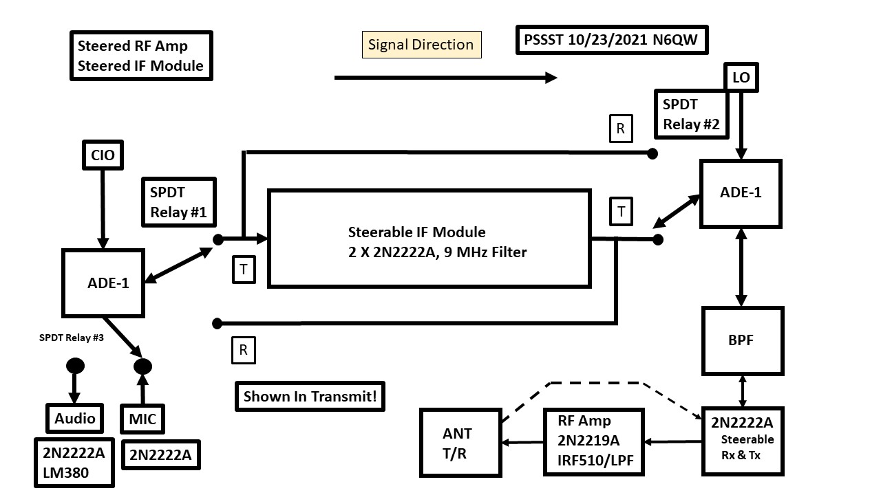
The Arduino Code will be provided for either filter frequency. Optionally the Spectrum Comms Filter matching can be either 50 or 800 Ohms -- I will also provide matching transformer data for either impedance. The 10.7 MHz Filter is a particularily excellent choice if 17M operation is contemplated. It will also work FB on 20M. Do Not Build your filter for this project as there is a high probability it will suck! For my build I used a 9 MHz GQRP Club filter (no longer around) but its match is 500 Ohms in out. This is the easy 19 to 6 match. 19^2 =361 and the 6^2 =36 thus the 361/36 = 10:1 which is a match to 50 Ohms. A 50 Ohm match is a 1:1 and 800 ohms is a 16 to 1 easily done with 16 Turns and 4 Turns. 16^2 = 256 and 4^2 = 16. Thusly 256/16 = 16:1 and match from 50 Ohms to 800 Ohms. The cores are FT-37-43 and the wire is #26 enamel. When Halloween rolled around my four kids would always ask about making their costumes and I would answer: First you start with a Poncho. Well all of my projects start with a block diagram. This project initially started as a simple solid state transmitter to replace the W4IMP 3 tube transmitter. But after a bit of noodling on the matter, I then saw the possibilities of expanding it to a simple transceiver using Solid State Devices. The first thing that should catch your eye from the inital Block Diagram is the use of the 2N2222A transistor at 5 locations. Added to the mix is a 2N2219A and one IRF510. So why the 2N2222A instead of the 2N3904, when the latter actually has a higher device dissipation (625 mw versus 500 mw). A really good question but this is where studying the data sheets pays off. Firstly, the 2N2222A comes in the metal TO-18 case style which means it can be fitted with a heat sink. Do Not use the TO-92 version of the 2N2222! The circuits run hot and you need the heat sinks! Another factor is continuous current draw -- the 2N3904 is 200 ma whereas the 2N2222A is 500 ma. Oh, another reason -- the 2N2222A is related to the 2N2219A (same die) only a different case style BUT their power dissipations are different! See 2N2222A/2N2219A Many of my designs use the 2N2219A as the Driver transistor for a IRF510. Recently a project of mine was built by the VWS (Vienna Wireless Society in Vienna VA) and contacts were made on 40M using just the 2N2219A. Let me not kid you --the design will try to squeeze every bit of juice out of the circuits and having a heatsink and higher current draw is important. The Ft cutoff frequency for either device (2N3904 or 2N2222A) is well above where it will be used. So how does this work? Not shown is a TR relay where the NC closed connection goes to the Receiver RF Amp stage and from there to a relay connecting it to the Band Pass Filter. On Transmit the TR relay shifts over from the NC (receive) contact to NO (transmit) connecting to linear amp stages. The Band Pass Filter connects to the ADE-1 but is switched to either of the two ( Rx and Tx) RF stages. But it is at the Band Pass Filter where some "Magic" occurs. The magic is in the form of a steerable IF Module comprised of two 2N2222A amplifier stages with a filter in the middle. The key here, as opposed to the bilateral stages so commonly seen in popular topology, is a single pass system that sends the signals in one direction. What changes during the transition from receive to transmit is what is connected to the input and output ports of the IF Module -- ie signal steering.
So, lets follow the signals! On transmit the output of the microphone amp is fed to an ADE-1 (Acting as both a Balanced Modulator and Product Detector.) where the DSB signal is sent through the IF Module where USB is passed (because of the BFO Frequency chosen) on to the 2nd ADE-1 which is the Transmit Mixer stage and mixed with the LO which is operating above the incoming outgoing / signal frequency. Thus a subtractive mix and sideband inversion and on to the Band Pass Filter. The additive mix is way above the Band Pass Filter range and is not passed. A word here about BFO frequencies. Because of the subtractive mixing to get to the signal frequency and assuming USB -- the higher BFO frequency (above the Filter Center Frequency) is used. On Receive the signal from the antenna (through the TR) goes to a moderate gain Receiver RF Amplifier on to the Band Pass Filter into the Rx/Tx Mixer stage. Here the signal is steered to the input port of the IF Module and the output is fed to the ADE-1 now working as a Product Detector and on to 2N2222A / LM-380 Audio Amplifier Module. My testing has shown with the minimum of devices it was nesessary to step up the system gain via the audio stages. Noteworthy is that the BFO and LO frequencies are generated via an Arduino Nano / Si5351. An added bonus -- the BFO/LO signals are connected to the same ADE-1's in either Receive or Transmit. We haven't turned on the soldering iron (one of the last things we do); but we have spent a lot of time with LT Spice. I have identified four separate circuit configurations for the 2N2222A transistors. The first is the Microphone Amplifier stage where I looked carefully at the low end frequency response -- so the audio doesn't sound "tinny" or pinched. Next was the IF amp module with the two 2N2222A amps. Of consideration is that the Crystal Filter I used has a Zin/out of 500 Ohms. So the IF Module stage considered that aspect. The simulations show about a 42 dB gain but we must also consider the filter loss of perhaps 6-10 dB -- so the net IF Module gain is > 30 dB. The third 2N2222A design was the Receiver RF amp stage with a gain of around 10 dB. It is an untuned stage for several reasons. Stability and Simplicity are the two operative words. This design is good to 30 MHz and doubles as the same design for the Transmit Pre-Driver stage. The fourth design is for the Final RF Amp Stage. Let me not kid you -- this stage is being run balls out and needs a heat sink! My goal is 13 Volts PTP which is around 400 mw. [13^2*2.5 = 422.5 mw). It would take about 90 ma across 50 Ohms to produce 400 mw. Now if we assume 50% efficiency in the device that would mean 180 ma to produce 400 mw. Thus you can see my choice for the 2N2222A. While four designs are mentioned there are 5 applications as the Microphone Amplifier is replicated and used as the Audio Pre-Driver This is a starting point for our SSB Transceiver design and undoubtedly will require revisions. The simulations look good ~ but real hardware performance is the test that counts.
The Steerable Amplifier
After some initial testing I remembered something from another transceiver project where I had a "steerable" amplifier stage that on Receive was the Receiver RF Amplifier stage; but on Transmit this stage became the Transmit Pre-Driver Stage. This has some charm so that following the steerable stage is a 2N2219A used as a driver which now produces about 125 mw and for a final the standard IRF510 so that the rig will produce > 5 watts. This makes it have more appeal as a minimalist rig than a 100 mw unlicensed "CB walkie talkie."
The PSSST Project Build
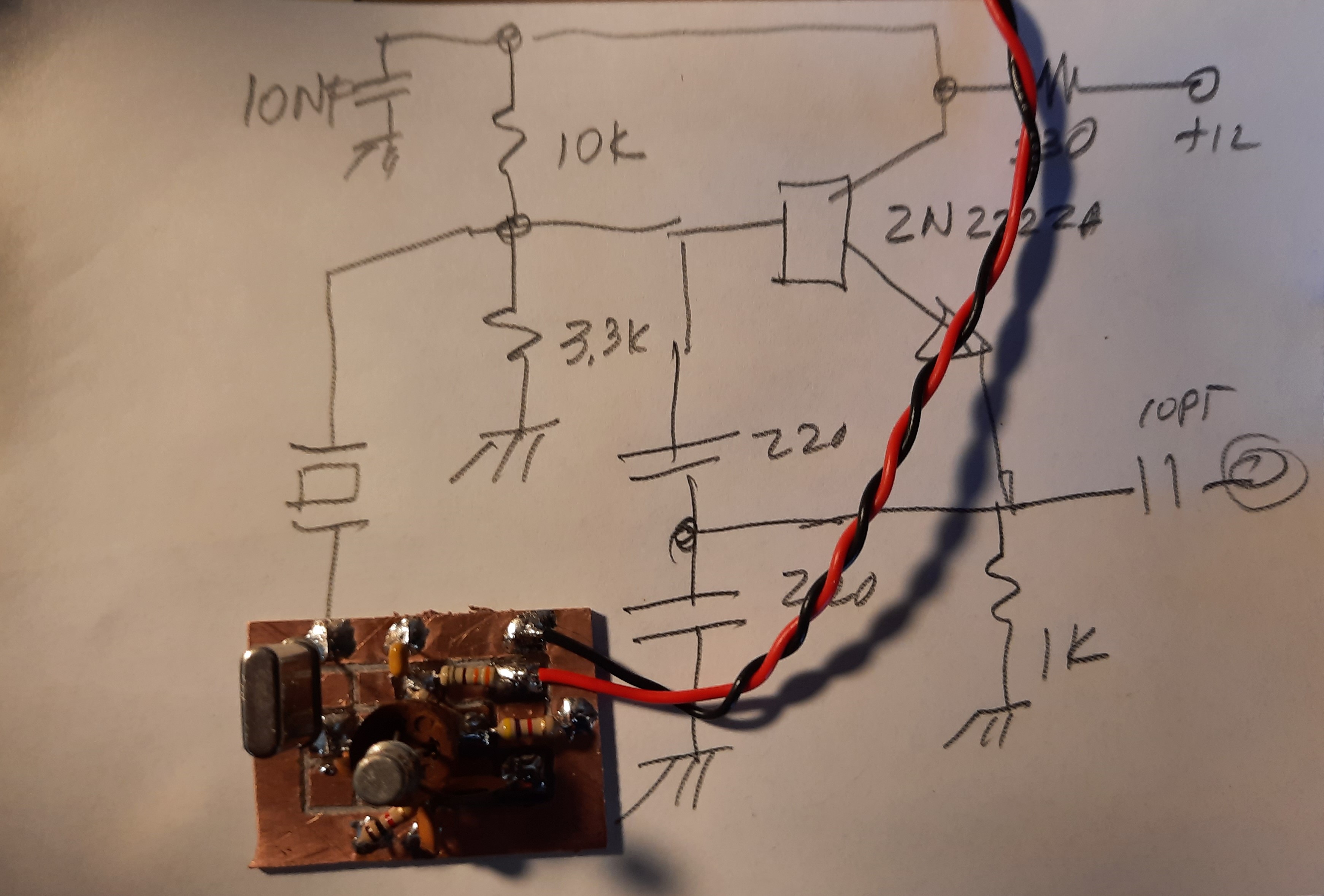
Before I present the fabricate/build details, I want to stress the nesessity of having some test equipment to determine if something is working or not. Two such devices can be built for pennies and work very well. The 1st is a test oscillator to determine if in the last go around you smoked some transistors. It is also good to test devices (thinking they are good when they may be duds) before installing them in a circuit .
This Test Oscillator was built for another project (over 12 years ago) and I ended up sending it to an Extra Class Ham that couldn't get his to work --yes, he had piss poor soldering skills! So today I gathered up some floor sweepings and built another one only this time with a 14.060 MHz crystal. So now you get the drift (no crystals don't drift) -- not only will it test transistors; but also can be a weak signal source for testing and peaking the Receiver. I love "twofer's".
It took about 15 minutes to build including milling out a copper board. See the following link for the current build of the Test Oscillator.
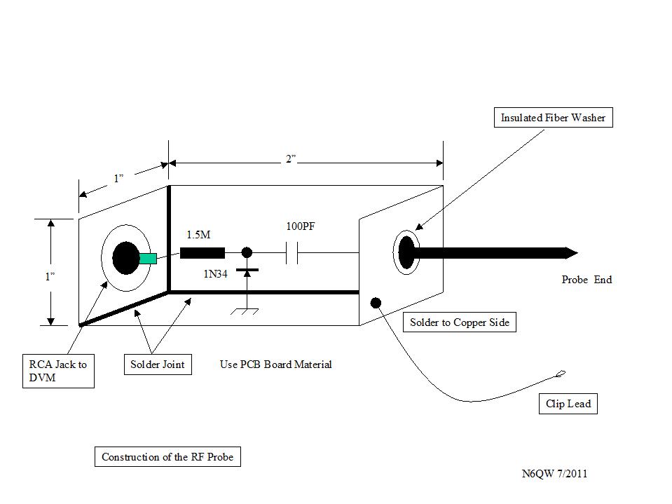
The second piece of home built piece of test equipment is an RF Probe that is attached to your DVM. This is a crude level O Scope substitute. But what it will do is give you indication that RF is present and to determine relative magnitudes of RF. The readings may not be super accurate but it is the relative readings -- like tweaking and tuning a BPF results in more output. That can be very useful. See this link for a sketch of the RF Probe.
[Yes, that same Extra Class got this along with the Test Oscillator as he could not understand how to wire it up. I hope he never takes off the cover of his IC7300! I was too late in realizing that I should have not sent him those two items -- he will never learn by someone just handing him the gear. Help is one thing -- enabling ignorance is another!] Another "tester" is a general coverage receiver with a BFO. With such a receiver you can see if an oscillator is oscillating and also where is it oscillating -- it doesn't have to give you a readout to 5 decimal places (like those that tout the Nano VNA); but you would know if it is close to 7.2 MHz and that it is oscillating. Another result of the test -- how does it sound? Does it sound clean? It is a like a go no go tetser.
The Build/Fabricate Noodling Process
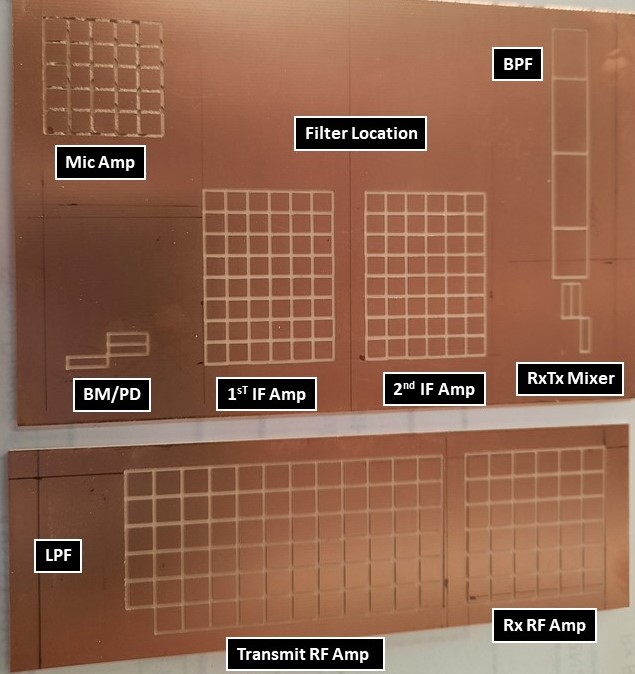
Often you will hear me speak about noodling which is time spent with the Soldering Iron in the "OFF" position and you use your brain to think about the project. I keep a notebook and pencil handy to jot down notes as I go through the process. My "noodling process" resulted initially in the concept and design of two boards with the island squares to house the circuits. The main board is 4 X 6 inches and the secondary board is 2 X 6 inches. The secondary board will house the Rx RF Amp and the Tx Amplifiers stages and the Tx LPF. All other circuit elements except for the LM-380 audio amp and the Digital LO/BFO are on the Main Board. The plan is to have the second board be mounted vertically and directly behind the Main Board. See this link for the layout of the two boards I fabricated for the main transceiver. The Main Board shown in the link identifies the circuit block elements; but importantly the circuits are built in the form of islands. This is done so individual circuit changes/improvements can be done on a specific island. The squares were made "large' just in case I need to make changes. My initial approach for the audio stage was the LM-386 Packaged Modules after several ham friends (N2CQR, G4WIF) had purchased similar boards on eBay -- essentially 10 Boards for $10. They have had great success with those boards. The one I bought has the volume control mounted on the board and the whole assembly mounts on the front panel via the pot. It also uses a different amp IC. I was excited as I saw some possibilities for space conservation. But initial testing has proven the module I bought as unsuitable. As I said it is not the same one as used by my friends; but just does not have enough audio gain. Think of a Limp ... Good enough for high quality earphones; but not good enough for the $2 CVS specials. So my initial approach of two boards changed and I fabricated a third board. A look at my milled crcuit boards may- cause a small panic -- don't panic! So sit down and if you are a member of the GQRP Club search on Club Sales and you will see the MePads from Rex Harper, W1REX [ qrpme.com ] that sells the island squares, in sheets, so you can just break off what you need and super glue those to a piece of copper PC Board. So you can make the same boards like mine, without having to use a CNC Mill. You can also go to W1REX's website.
Build and Test As You Go!
My thought process led me to a logic sequence of "Build and Test" as you go. The worst thing you can do with any project is to solder everything in place and power it up only to find out it does not work! It also may result in a small smoke cloud on your workbench. If you build small pieces and "test as you go" then you have that well in hand so that before you install the last piece you know up to that point --everything works. [When I worked for a living I attended a manufacturing executives conference and as luck would have it sat next to the guy who ran the Toyota US Assembly Plant. We chatted a bit about how we ran our manufacturing lines (I was building military aircraft [F-15, F/A-18]; but our processes were similar, however, his had a few bonus ideas.). He mentioned that every 100th car on the line went through an automated special inspection process. I quickly asked isn't that expensive? He immediately said NO! Here is why. At that time he was shipping 2200 cars a day from that plant. He then said to me which would you rather do -- fix a problem on 100 cars or 2200 cars. That is when that concept snuck into my hobby -- test as you go.]
My noodling process led me to sequencing the builds starting first with the Digital LO/BFO. When I am ready to start some testing it will be available as a part of the test process. (Shades of Heathkits!) My LO operates above the incoming / outgoing signal frequency by an amount of the BFO. So while the dial says 14.2 the LO is operating around 23.2 MHz. Now if I crank the dial so that the LCD reads 5 Megahertz --the LO is spitting out RF at 14 MHz and that now becomes useful for some testing. The next Board is the new 3rd Board -- the Audio Amplifier. This will have to be moved up on the build sequence because of the poor results with the packaged Audio Amp model that I bought. Think for a minute -- with the LM-380 Audio Amplifier and Digital LO/BFO we would sequence the follow on builds so that the Band Pass Filter and the ADE-1 Receiver Transmitter Mixer stage would be installed. With just those two parts plus the Audio Amp and the Digital VFO (cranked down so that the LCD reads 5 Megahertz) I would have the makings of a Direct Conversion Receiver on 20 Meters. So that would be a test point and having the Digital VFO enables such testing. If that all works as a DCR then check those moudles off of the list. Our Test Oscillator at 14.060 MHz would be a local weak signal source -- is that a "fourfer" ? At the other end of the board, by building the Microphone Amp and connecting the ADE-1 DBM used as the BM/PD, I now can test for a Double Sideband Signal coming out of the ADE-1. This is a key point -- with the actual building of the Band Pass Filter and the Microphone Amplifier I am able to test a good deal of the transceiver. This test as you go essentially is a check off list. The real heart of the build is the IF Module and steering relays. The work to this point when completed now gives us about 75% of the whole transceiver and that is all on this mainboard plus the Audio Amp and Digital LO/BFO assemblies. Another nonus of this approach -- the testing of this subsytem -- if all works (ie receiveing a weak signal and having a SSB signal at the output of the BPF) Then the only issues when the full transceiver is complete is the Rx RF Amplifier and the Transmit RF sections. The last two on our list (Items 6 and 7) are contained on the second board that houses the Receiver RF Amp stage and Transmitter RF Amplifier section.
Steps to a Successful Construction
Getting organized for the build / fabricate stage is as important as the circuit design. Too many homebrewer's start off a project woefully lacking even the basic tools and the right parts. A 10K resistor is not a good sub for a resistor specified as 47K. When it comes to tools I recently have shifted over from my expensive DVM to a good quality VOM. (One costing about $30 versus the $9 Harbor Frieght one). If I smoke it, I will be mad but not as mad as smoking the $175 DVM. It works well. I also have a Siglent 100 MHz DSO and FeelTech Signal generator and an Audio Range DDS. One very useful tool is a homebrew SWR bridge and Power Meter. If you can wiggle the meter it is transmitting. I also have not one; but two Nano VNA's and I don't trust either one of them. You never get the same answer using the same circuit measured with the two devices and you never get a consistent answer on the one I think is working. So I would bypass the use of a Nano VNA and I do! Now, before the Nano VNA there were processes to measure Band Pass Filters. I did just that and you will see that in the link to the BPF. I centered the sig gen on 14.2 and terminated the BPF in 50 Ohms. I put my scope on that resistor and then peaked the trimmer for TFMS (tune for maximum smoke) at 14.2 MHz. Then I moved the sig gen up in frequency and down in frequency and noted where the signal dropped by 3 dB (half power) and then 6 dB (quarter power). A bit more time consuming -- but that I trust and so should you! My power measurements are consistent with the LT Spice simulations -- so no fuzz on this as there is with the Nano VNA's I have. When it comes to the LPF the same setup as the BPF will clearly show the cutoff frequency and that too can be simulated in LT Spice and compared for consistency. Avoid the Nano VNA --they sometimes lie! So before lighting off the iron have all of the parts in hand and have them segregated by the stages. I use plastic sandwich bags (see through) to collect the parts and then using my Sharpie Pen write on the bag the name of the modules for which the parts are intended, like Mic Amp, Audio Amp, BPF and so on. Equally important is the "quality process" before applying power which checks critical factors.
|
|---|