The Digital LO and BFO ~ Arduino + Si5351 and Color TFT
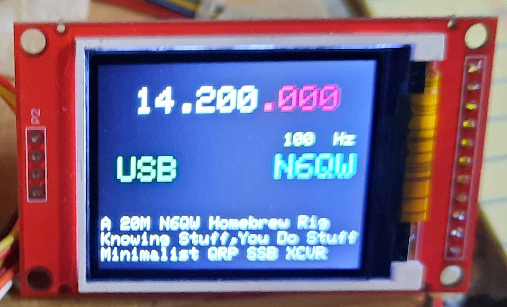
The PSSST started out with a 16X2 LCD and while we got creative we found having more real estate to display information was a huge bonus. The added icing to the cake ~ Color, lots of it. It also solved another issue. I noted with the LCD that the encoder would jump digits. That problems seems to be less with the Color TFT which perhaps says something in the code is the differential. The Wire List Link shows the Pin wiring to the Arduino and the Color TFT. Guys and Gals I am bristling a bit when I get emails asking if some cheapo display will work with this circuit. Like in the TV Commercials of Old I am NOT the Shell Answer Man. If you have a display then check the Pin out of your display to the wire list and that is you job NOT mine. Secondly my code uses the ST7735 Libraries. If you pick a Color TFT with the ILI9341 Code Set, then it is up to you to find the libraries and the wire correlation. Time to step up and figure out this stuff on your own. The capabilities of the Digital VFO includes selection of USB or LSB and various step tuning rates. Now embedded in the code is a selection of essentially two VFO's. I have set one so that start up is 14.2 MHz and the others is 14.074 Mhz. So at a flcik of a switch I check what is happening on FT-8 wihout having to tune down to that part of the band. But there is more to this functionality. If we use a DPDT switch we could use one half to control two different frequencies in two bands --such as either 40M or 20M. The other half of the switch could power on relays so that you would have a comparable BPF and LPF switched in line depending upon what band is chosen. The USB/LSB selection now has import especialy if cruising down to 40M SSB. So just with some embedded code and one DPDT switch we have a two band SSB transceiver. We are still using just 7 transistors. Bonus feature: TUNE Tone. Built is is a 10 second pulsed 988Hz tone that can be fed into the Microphone jack for tune up purposes. You won't find that in a BITX or QEX! There is no pad layout as Vector prototype board was used and the whole assembly was wire wrapped (this is digital not RF).
NOTE on the Arduino Code. If you want the Sketch Info then send me an email to craponthebench@gmail.com By doing it this way I can gage how many homebrewers are working on the project. Or if you are so inclined --write your own code.
|
|---|