A Wireless Set for 2022 When I hear the term "Wireless" it immediately conjures up a view of a grainy black and white WWII 1940's British Spy Movie, replete with a dimly lit room and a radio set built into a suitcase. The operator is using his/her Wireless to send coded messages either to/from the UK. It was not only a wireless but it had many knobs and "valves"! [Initially the US Navy had control of radio operations in the USA. LINK In 1912 the US Navy changed the term "wireless station" to "radio station" . The US Navy, as only the US Navy can be, was perturbed by the Hams invading their radio space. The Navy had a law passed that said Hams could only operate 200 Meters and down. What a Gift!]
The idea to homebrew a "Wireless" was prompted by a recent viewing of such a spy movie on You Tube. [The movie is Cloak and Dagger with Gary Cooper.] Wow what a hoot. But those radios were typically low power CW jobs. But how about a Wireless Valve QRP SSB transceiver and thus the torch has been lit! I should start by saying here is the first inhaling of signals.
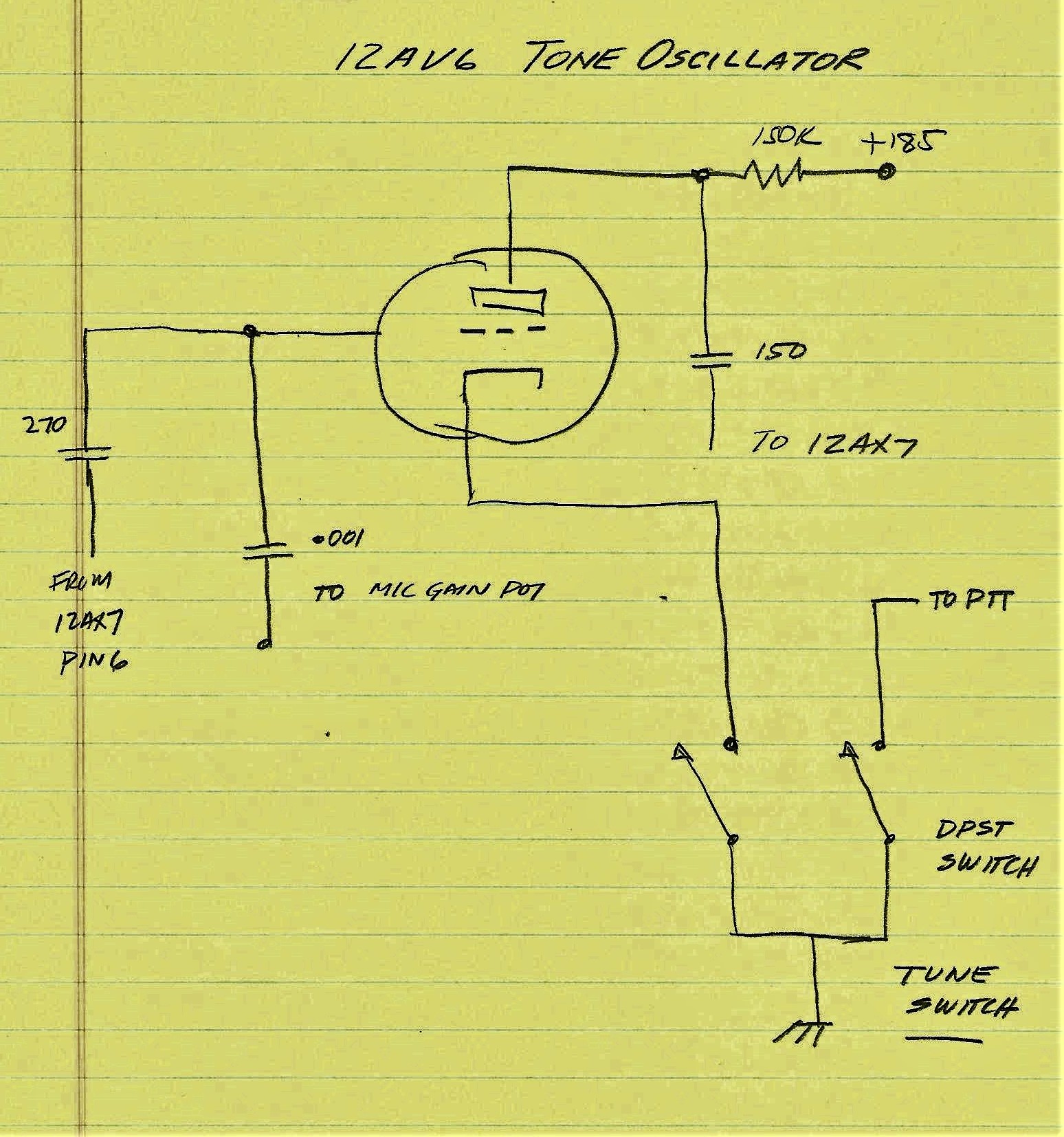
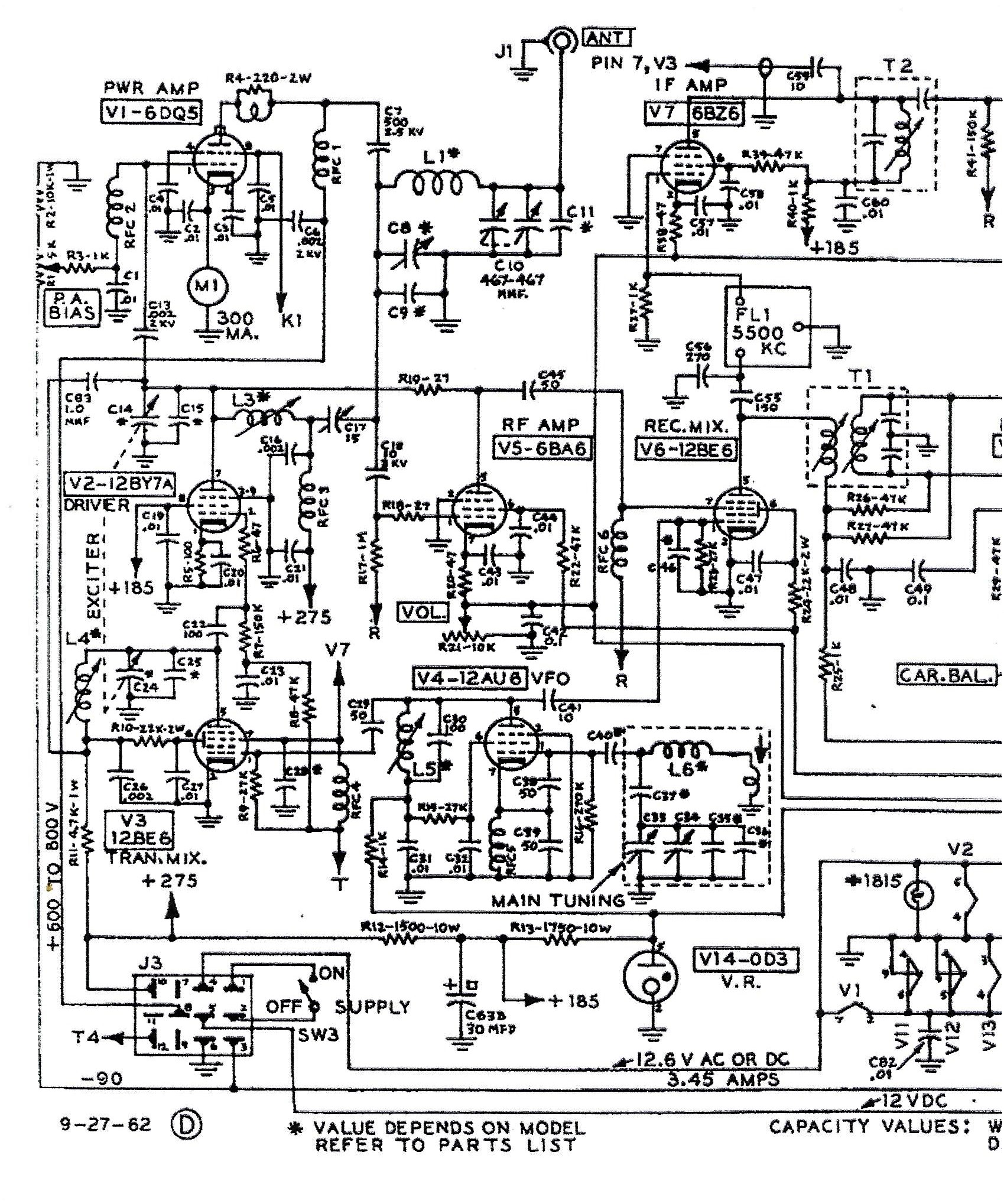
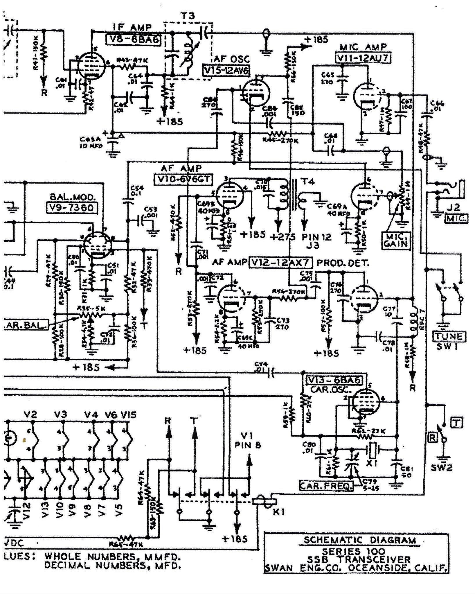
But first a bit of discourse on why build any rig with tubes in the design. The answer is simple -- just to be different and to not be like others who only homebrew rigs that can trace their pedigree to a Bitx20, EMRFD, or built around TIA stages. In earnest, I want to prove using other mediums that a successful mostly tube SSB Transceiver can be built without being tethered to these overworked and often quoted designs (Bitx, EMRFD and TIA)! There are other reasons too and these include the availability of many of the tubes of old at cheap prices and even hulks of old rigs can be found at ham fests and on the auction sites for literally less than a tank of gas. Yes -- using old technology with a bit of modern magic a Wireless Set is born! While the roots of my Wireless lie in the Herb Johnson (W6QKI SK) Single Band Series 100 Transceivers of the early 1960's, there are many significant modifications that update the rig to 2022. (SW-175, SW-140 and the SW-120 comprised the Series 100) A bit of a word or two about the Series 100 Transceivers as manufactured by W6QKI. Firstly it was an amazing product that enabled many hams in the early 1960's to get on SSB without spending 3X the cost of a Collins KWM-1. SSB rigs for the masses as at price you could afford -- what a concept! It was a simple design that got you there, but did cut a few corners in doing so. For one the sensitivity was not what we see today nor what was available in much more expensive radios. The other issue was the use of a rudimentary 4 pole Crystal Filter. The filter bandwidth was likely a bit wide and the pass band ripple much like an adolescent boy with terrible acne -- lots of bumps and not as smooth as a baby's bottom side. My "wireless" will have a better crystal filter and perhaps a better sensitivity based on not using the Pi Network Tank as a front end. Let's face it when using such an approach there is a compromise in that we always shoot for maximum power output which may not be the same point for maximum sensitivity. The SBE-33 Transceiver comes to mind where you make that same compromise between Power Output and Peak Signals. My design will have a Band Pass Filter on the very Front End of the Receiver and a similar BPF following the Transmit Mixer Stage. In a later version of the Series 100 a Tone Oscillator was incorporated into the design versus the earlier approach of simply unbalancing the 7360 Balanced Modulator tube. The 12AV6 (Tone Osc) approach used a DPST panel switch where 1/2 of the switch is connected between the 12AV6 Cathode to Ground (on state) and the other 1/2 tripped the PTT. This is a typical Herb Johnson approach in that some radios that were on the line being built as per the original design but had the Tone Oscillator installed. In some of the Series 100 transceivers the tone oscillator was fitted to a small L Bracket that was mounted underneath the chassis -- sort of stuffed into the wiring. Great idea Herb! Using a bit of modern magic a SPST switch connected to the Arduino inputs a signal where on the TFT Display it says "TUNE" while simultaneously making a Pin HIGH to close a DPDT relay which will "On" the 12AV6 and trip the PTT. If the availability of Arduino Pins was a concern then a DPST switch could simply input to the Arduino (1/2 the Switch) while the other half controls the relay. A discussion of homebrew "valve" SSB Transmitters and Transceivers would not be complete without a "Tip of the Cap" to Mike KG7TR who is not only a master craftsman but has produced some really stunning looking rigs. Visit Mike here Please refrain from comparing my pile of junk to anything Mike has built -- he has knack extraordinary!
My Wireless ~ The Build
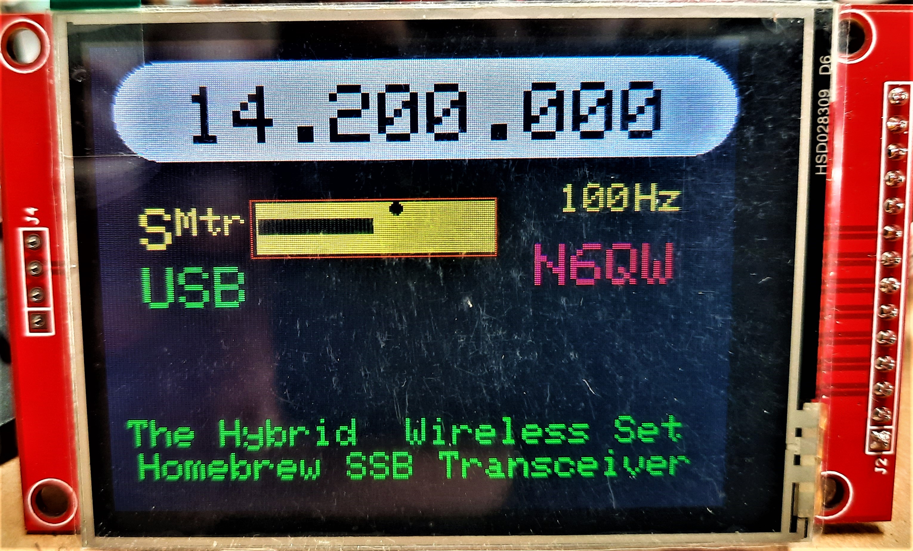
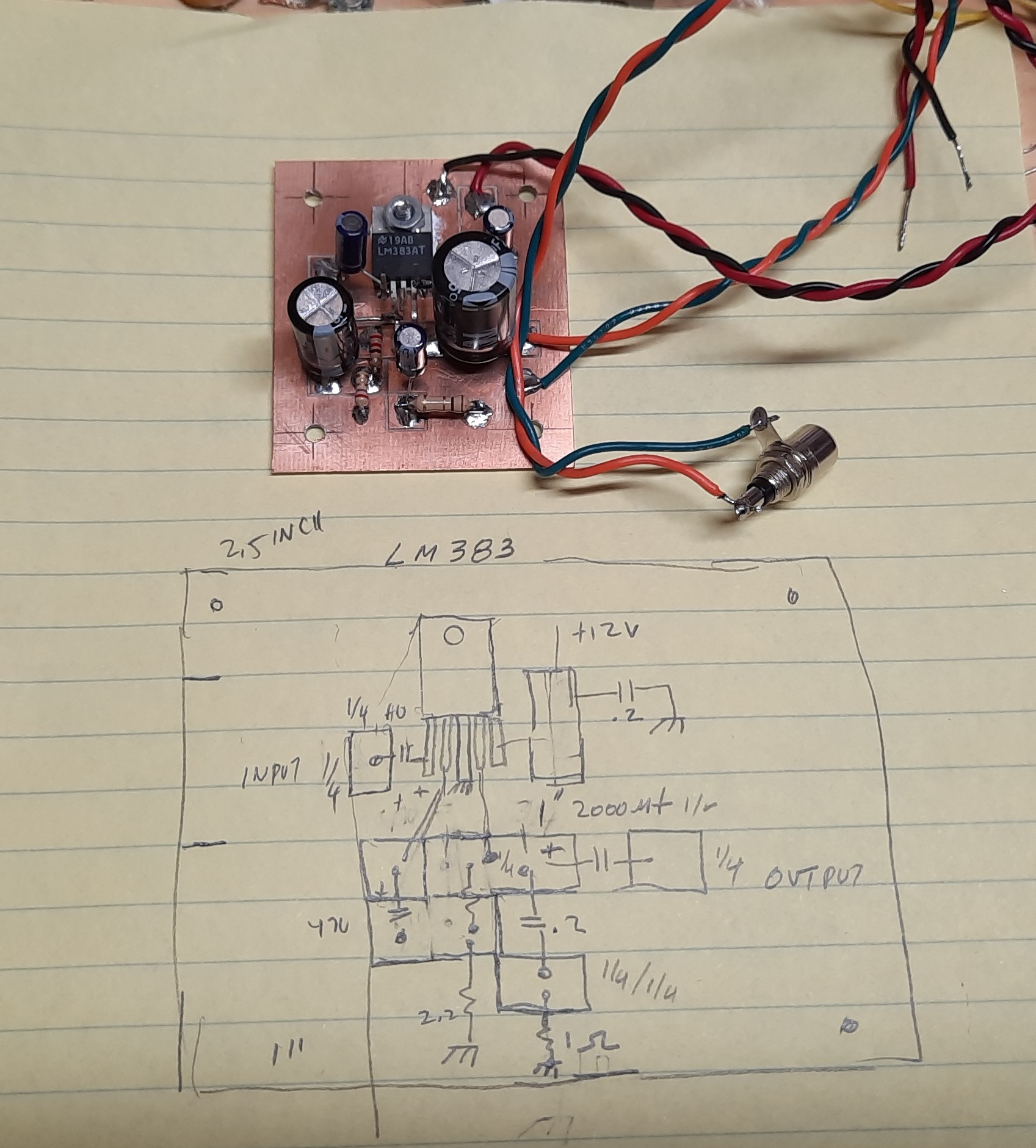
But 1st a PSA as with any project we identify issues to be resolved and accordingly I have identified certain issues and will track the items and resolutions. For SW-120 update starters, I am using a 3.2 inch ILI9341 Color TFT (see video) that along with the Arduino/Si5351 gives a highly accurate and extremely frequency stable on the air signal. The use of broad band tuning eliminates the "dip and load" process when you QSY. A robust LM383 audio amp leaves no question about room filling volume. The RF output will be 15 watts --more than QRP and capable of driving a 300 watt SS Amp from CCI.
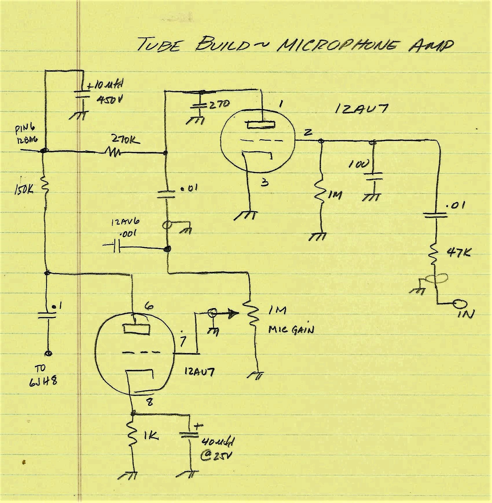
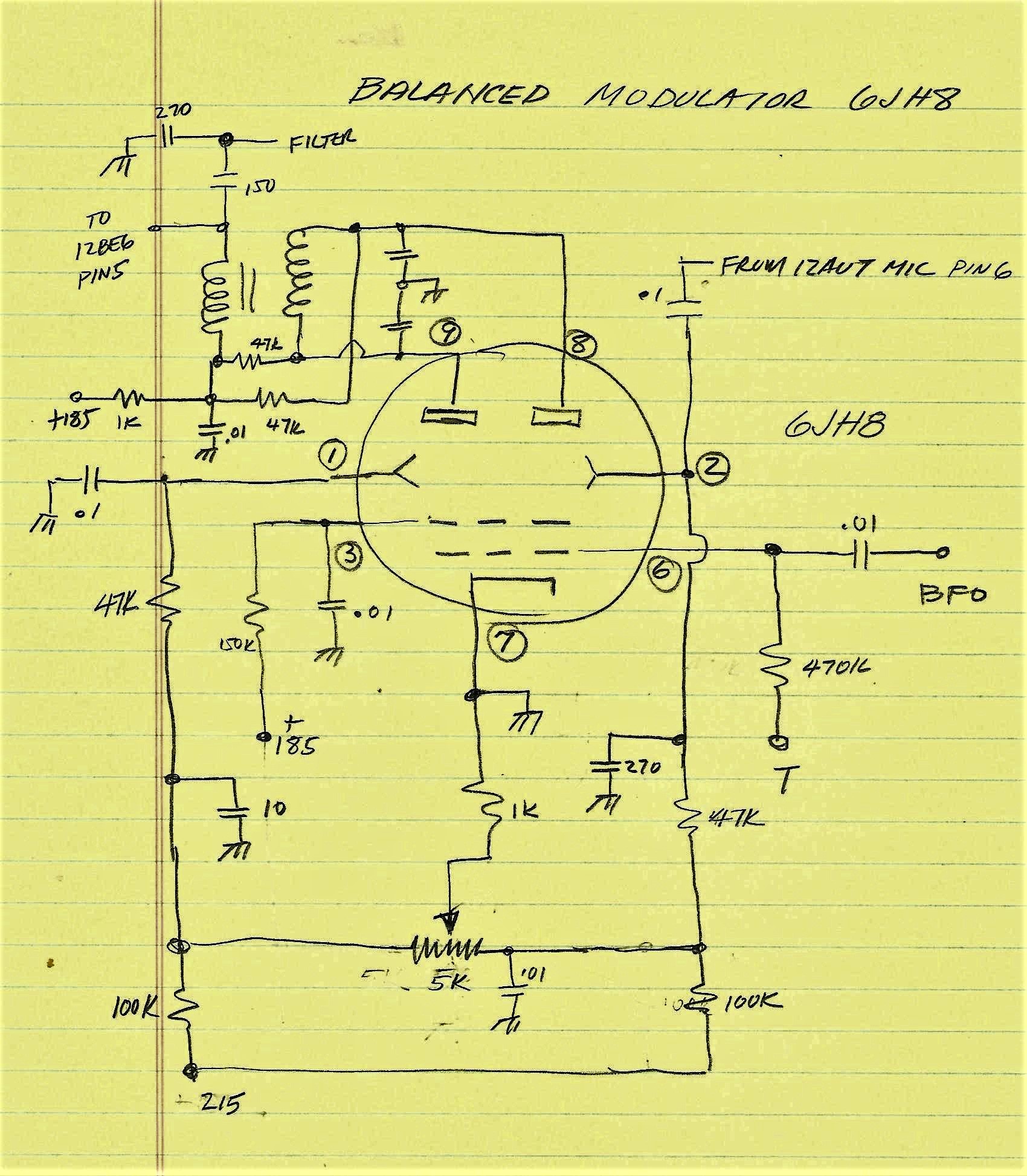
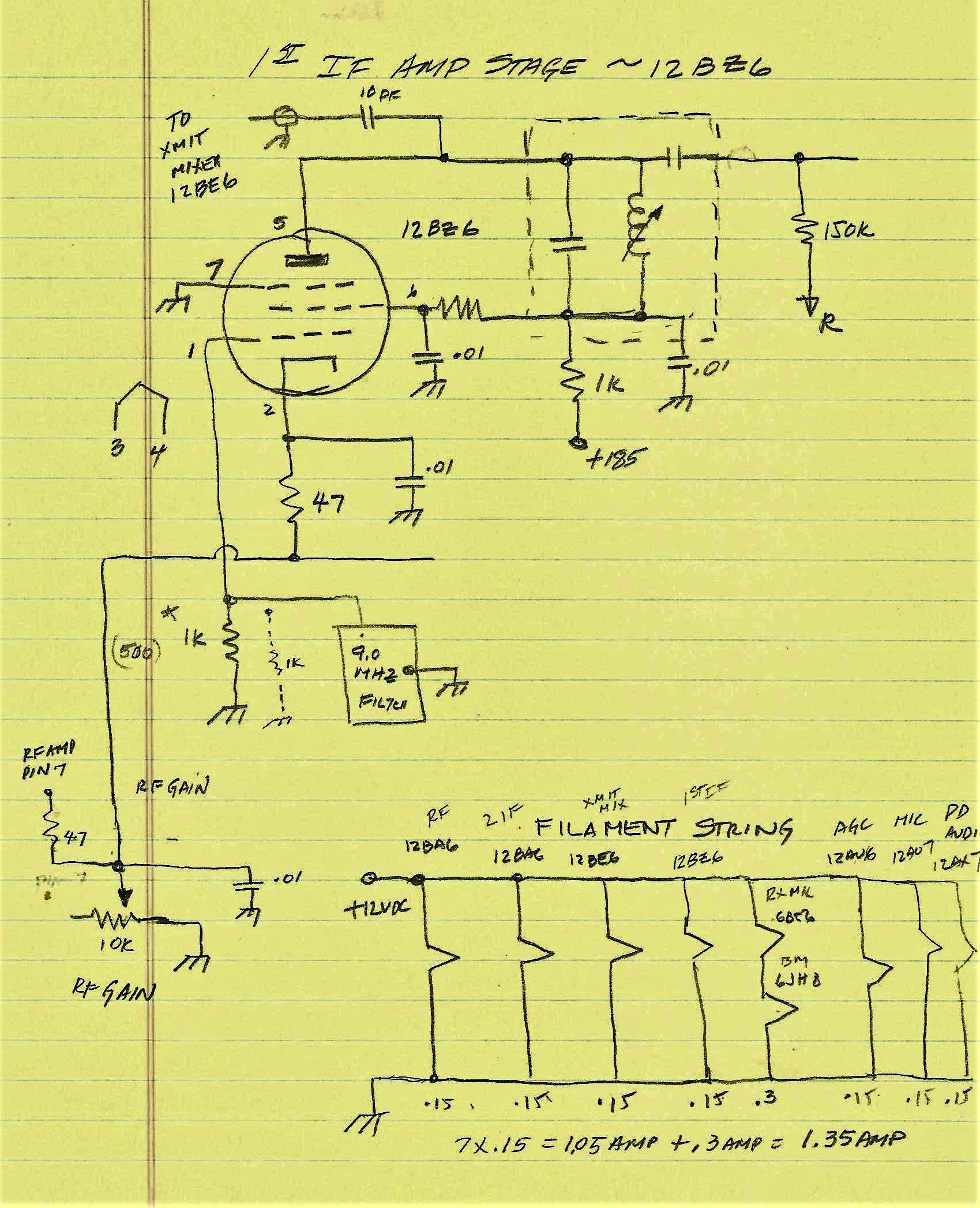
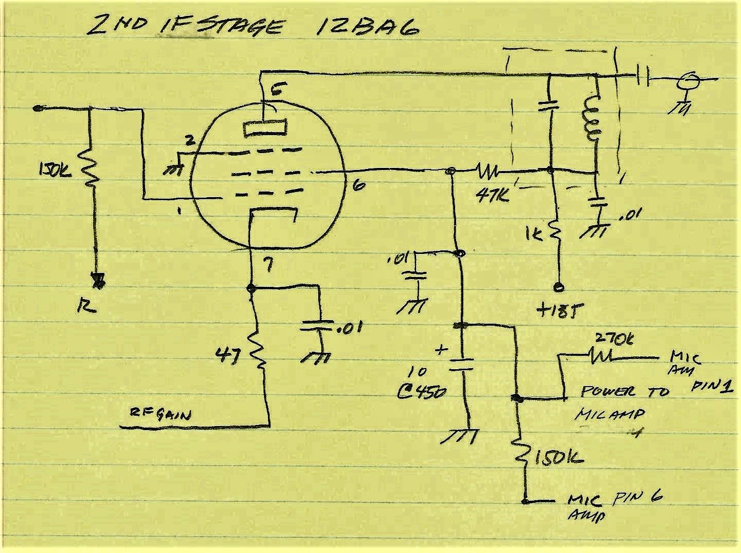
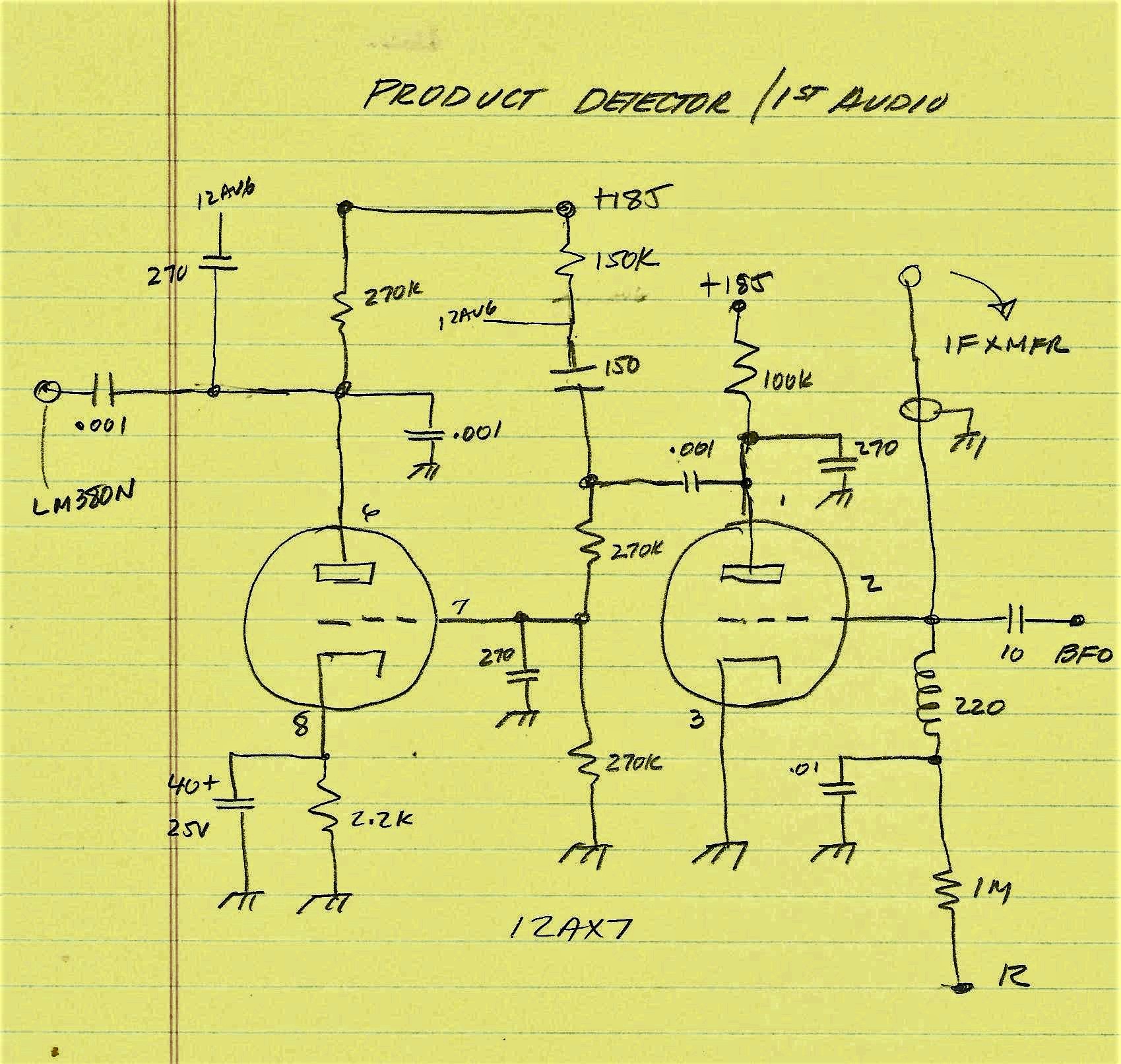
The Architecture of the 1950's -1970's tube rigs was not unlike a follow the sheep approach of the day (similar at that time to Bitx20, EMRFD and TIA) where most of the designs had a 12AU7 Microphone Amp, a 12AX7 Product Detector, A 12BZ6 in the IF chain, 6BE6 or 12BE6 as the Mixer stage and of course 6BA6 or 12BA6's in the RF/IF stages. The Audio stage had a 6V6 or 6AQ5 or like Heath and Collins a 6EB8. For a Balanced Modulator either a Diode Ring with Germanium Diodes (1N34 or 1N60) or tubes such as the Sheet Beam variety like the RCA 7360 or GE 6JH8 or 6AR8. The 7360 got to be very expensive so many radio manufacturers switched to the less expensive GE types (6JH8 or 6AR8). Swan made the switch in later radios like the 350 and 500. Even today that is the case with the price of these tubes. A 7360 may fetch $50 whereas the 6JH8 can be found for under $10. A note in history, GE was a major stock holder of RCA and both produced vacuum tubes! [In 1919 the US Navy gathered AT&T, United Fruit Company (UFCO now Chiquita Banana), GE and Westinghouse to form RCA with GE as the major stockholder. In 1926 RCA bought a radio station from AT&T and created NBC. One might ask why Chiquita Banana was in the radio business -- simple it was a technology tool needed for the conduct of the banana trade! UFCO had an extensive investment in radio stations, technology and shipboard equipment. The US Navy caused this action because of national security issues seeing as much of the early high power radio gear was made off shore and WWI demonstrated a huge vulnerability. See the earlier link to the US Navy. ]
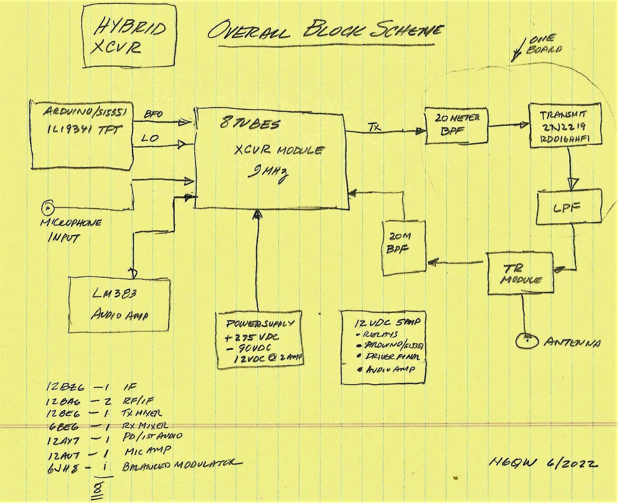
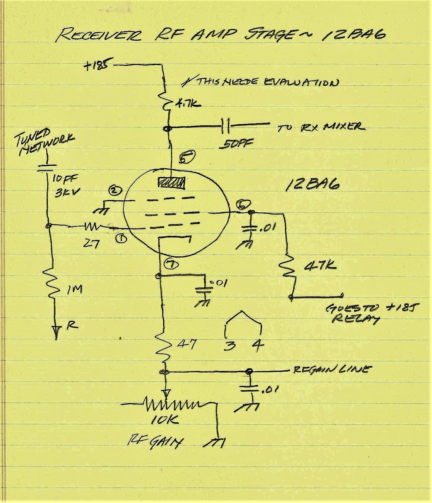
My view (above) is sort of a reverse to what was done with the integration of transistors and tubes. Typically those designs of the 60's/70's had solid state devices in the lower level stages and because of the lack of high power RF devices the Driver and Final were tubes (valves). As is typical from N6QW, I am doing the reverse. All of the low level stages are tubes and certain of the other circuits are solid state. The LO/BFO = Arduino/Si5351/Color TFT, with the Driver and Final being the 2N2219A and the RD16HHF1 (15 watts) and the audio will be a robust LM383, a 7 Watt Audio Stage. Some noteworthy points about my design. The first is taking a tip from Joe Carr (Chapter 4 in the reference) who strongly supports using a Band Pass Filter ahead of the front end. Simple approach: only process the band of choice keeping out of band signals from the front end and preventing overloads. The second is to have a moderate amount of gain in the front end so that you are amplifying the signal and not just a lot of noise. Balance grasshopper. [Reference: The Technician's Radio Receiver Handbook, 1st Edition December 27, 2001. By Joe Carr.] My approach is driven in part by something from the 1970's, when I attempted to build a compact version of the Swan SW-120 single band SSB Transceiver. The chassis was really small. I did build it -- but it did not work too well. I kept the chassis plate and that is the basis for my wireless project. The plate on the left is from 1970 and the same plate reworked is from 2021. (Yes a CNC Mill is very handy!)
Tube/Chassis Layout (Those with inquiring minds will ask why mostly 12 Volt Filament tubes but two 6 volt Filament tubes in the mix. The 6JH8 only comes in a 6 volt version and requires 300 ma of filament current so that the filament string can be run off of 12 volts requires additional current balancing. Thusly, another 6 volt filament tube with its filament connected in series is used. Luckily the 6BE6 has a 300 ma filament requirement. Thus the reason. The 7360 was an odd duck as it requires 450 ma of filament current --so a bit of a juggling act to get all the filaments lit .)
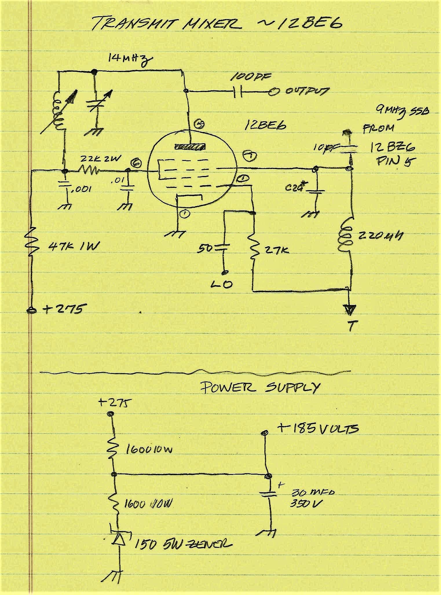
I did not start with a clean sheet of paper and because the metal plate is mostly laid out like a Swan SW-120 that is the template. Thusly I am planning on using much of the core design of the SW-120. The significant change is the use of a 9 MHz Commercial Crystal Filter and a change from the 7360 to the 6JH8. Then of course all of the off-board circuits such as the LO/BFO/Display, the Audio Amp and the Driver and Final are all solid state. The power level is 15 Watts and with an outboard SS amp could produce 300 watts on 20 Meters. Did I mention that the Color TFT will also have an S Meter as a part of the display? One thing I have done to facilitate the build is that I decimated the original schematic into the individual pieces so that the build will be done by each stage. Particular attention will be paid to the sequencing of the build. First I will start with the LO/BFO Module as in itself it is a piece of test equipment. Next will be the Microphone Amplifier followed by the Balanced Modulator and 1st IF amp and then the Transmit Mixer. This will let me test the transmit output and look at the drive levels available to drive the final amp stages.
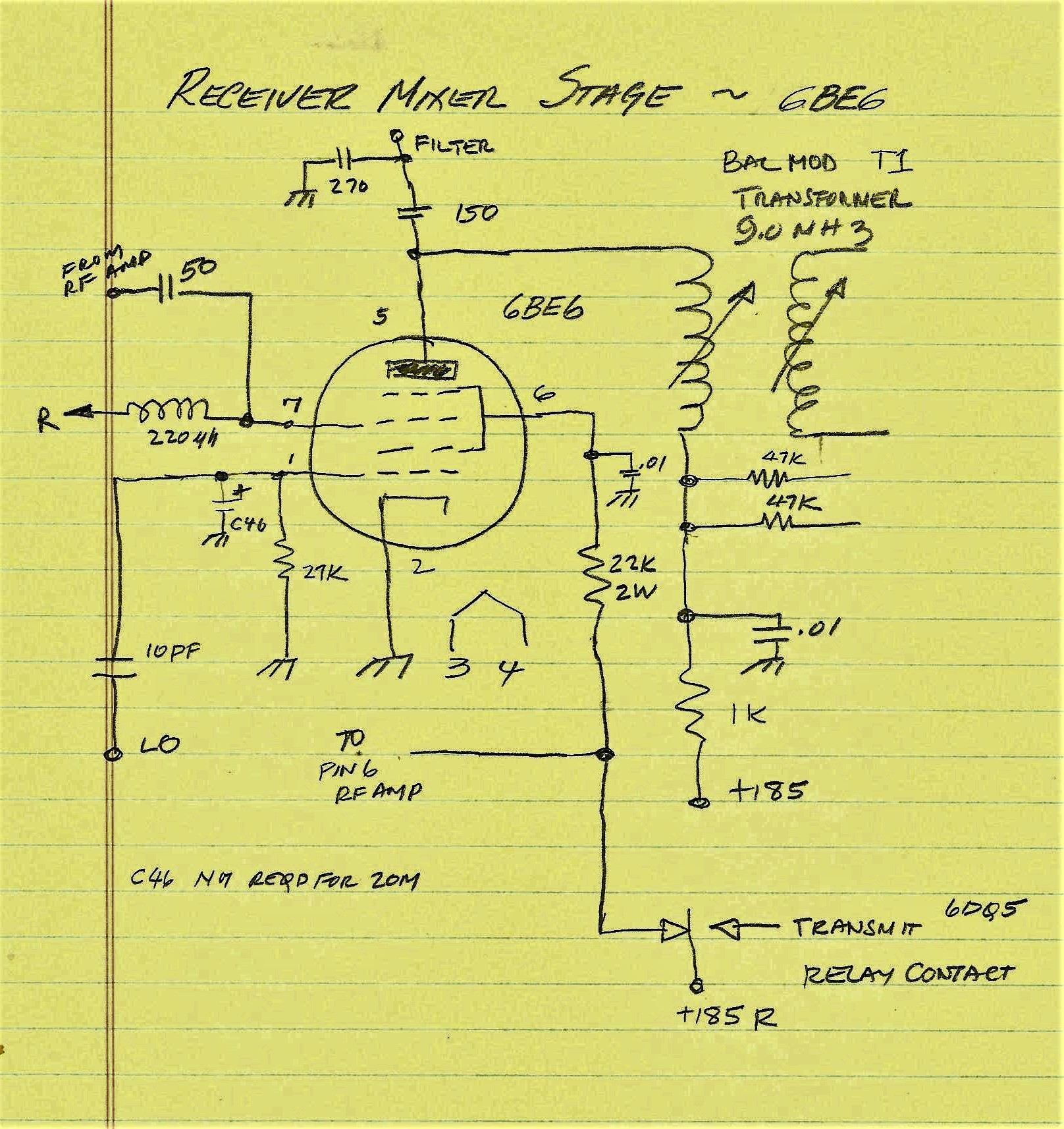
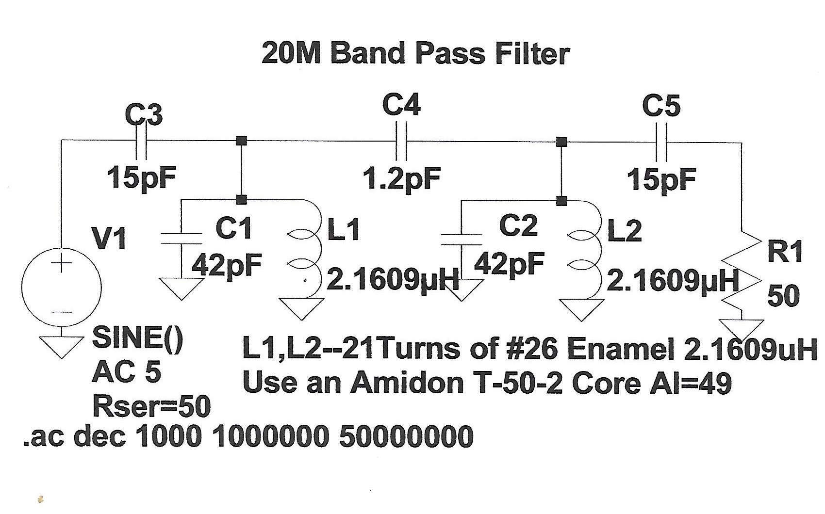
1. The Transformer in the Plate circuit is a 10.7 MHz IF Transformer. I will have to experimentally determine the values of the two caps to make it resonate at 9 MHz which is the IF. TRGHS -- I was doing some initial testing of the transformer and realized internally there were some caps soldered across the windings (2X 33 pF) . So I disassembled the transformers and in the process my FFS caused the cores to be jerked away from the solder lugs. Disaster or Opportunity? I simply removed the caps and removed the wire counting the turns (26 Turns). I then scramble rewound the two cores with 30 Turns of #34 enamel wire and taped the windings to the paper core. Before reassembly I tested that I had continuity at the pins and reassembled the can. The two 33PF caps were then used as the two caps in series with the common connection to ground. The reason for the two caps is to provide two outputs which are connected to the plates of the 6JH8 -- sort of like phased outputs. I tested the transformer by injecting a 9 MHz signal into the secondary and then with my scope could see a peak on either pin of the transformer to ground at 9 MHz. I think my disaster turned into a working balanced modulator transformer! Despite the aforementioned description -- my homebrew Balanced Modulator sucked on carrier suppression. I replaced it with another unit I found in the Junk Box and --Mucho Better. I also had to fabricate a mounting plate for the 2nd transformer. Thank God I have a manual milling machine! 2 . The IF Transformers must be resonant at 9 MHz and I need to experiment with the output coupling cap and for starters about 50 pF. These worked well with 47PF. 3. The BPF Design is shown elsewhere and two are built both identical and have a Zin/out of 50 Ohms. Had to diddle with BPF and the circuit interface -- it is not all 50 Ohms. The plan is have the power supply which is built for another use modified to meet the voltage/current requirements. We need 275 VDC at 100 ma, and at least -90 VDC Bias and 12 Volts DC at 3 amps for the Filaments and Relays.
I used a small 125 Volt to 125 Volt Isolation transformer for the Bias transformer. The DC output was nearly -160 Volts. So, collecting two 10 watt resistors one at 2.5K and the other at 4K the series combo gives a 2.5/6.5 ( 0.38) drop at the junction with the 2.5K connected at the source and the 4K to ground. Thusly, 0.38 X 160 =60.8 Volts drop. So the voltage at the common junction is -100 VDC to Ground. The value is acceptable for cutoff Bias. We have a supply!
A bit of development work is needed for the Transmit and Receive Mixer stages. The Transmit Mixer Output in the Original SW-120 was gang tuned with the Driver Stage so that you picked off the "Plus" mixing product. I.E. 5 MHz SSB + 9 MHz LO. I am changing that to a simple RF Choke followed by a 20 Meter two stage BPF. In my Wireless no tuning required and we only get the Minus mixing product (LO Above the Operating Frequency). I figure a 1000 micro henry Choke should be in the Ball Park. The impedance is 89K at 14 MHz so in parallel with 50 Ohms the equivalent is 50 Ohms. We might need to do some fiddling with this, but I think it is viable. A similar approach was used with the Receive Mixer stage so essentially the RF Amplifier is connected to the Low Pass Filter (limiting some of the spectrum being received) with output fed to a 20M BPF inserted between the RF Amplifier Stage and the Receive Mixer Stage. The Band Pass Filter covers from about 14.050 to14.350 Mhz. Yes, this Wireless will do FT-8 but essentially skips CW. CW = "C" What? On receive in the SW-120, the input was connected to the Transmitter Tuned network and the resonance of the Transmitter stages put the Receiver in the right frequency range. My plan is is to use Band Pass Filters which should add a lot to front end selectivity and a cleaner transmit output. Again another "fiddle" point. It is OK for the Nay Sawyers to point out this is a single band design which it is. Adding band switching is a complex matter and my design approach is to focus on one band for simplicity. Those who are thinking 17Meters - don't - not with a 9 MHz IF, but 15M would be a good second choice to consider. Given that what I see about Cycle 25 forget 12 or 10 Meters. My observations are contrary to some scientists who think we will have a booming >200 SSN. It seems like the Left Coast has been Left Out of that pipe dream! A general comment at this point -- tubes and solid state are decidedly different technologies BUT the problems to implement these two technologies are like close 1st cousins. I find when doing the SS schtick I am always having to adapt some feature or function even extending to mechanical installations. Having those skills are the exact same approach when working with tubes (like my Balanced Modulator Transformer rebuild). We fiddle with tube circuits just like we fiddle with solid state circuits!
BTW in the initial Receiver testing the front end was DEAD. The problem was traced to a faulty relay and a failure to connect power . On receive +185 Volts is supplied via a Relay to the Screens of the Receiver RF Amp Tube (12BA6) and the Receiver Mixer Tube (6BE6). The relay pin was not making a good contact so no screen voltage no signal. There was also no plate voltage on the Receiver Mixer (6BE6). On the schematic the plate voltage to the 6BE6 was shown as a part of the 6JH8 circuitry. I had not hooked up power to the 6JH8 because I was only testing the Receiver. Fixing those issues sure made a big difference.
|
|---|