The Sudden Transmitter Details |
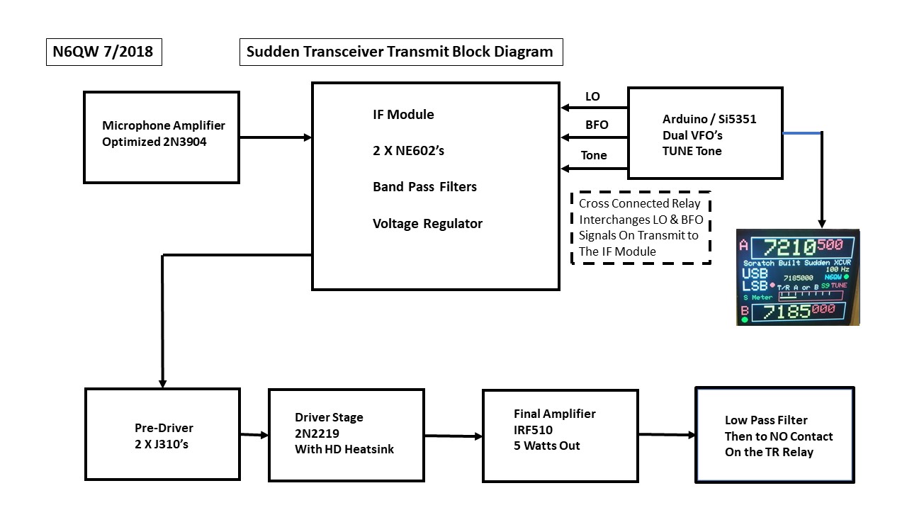
Because we have used a design where there are common elements on both transmit and receive, this section includes the addtional circuitry that turns receiver into a transceiver. This is done with just a few more boards. By way of review the Part I included common elements such as the basic IF Module, including the switching relays and the Arduino Nano /Si5531 plus the cross connected relay. These remain unchanged for the Transmit stages and the only exception to note is the switching of the LO/BFO signals to the NE602 #1 and #2 as you go from Receive to Transmit. But that is already built into the SI5351 PLL Assembly as wired in Part I. The Transmit Band Pass Filter installed on the IF Module uses the same component values as the Receive BPF and so the builder might want to install the Transmit BPF at the time the IF module is built. Thus we need only address the Microphone Amplifier and the Transmit chain beyond the IF Module. Also note that the 40 Meter Band Pass Filters can be used on 20 Meters with a simple mod. Lift the Ground ends of the four 150 POF fixed caps and retune for 20 Meters. Special Notice Here. There are four matching transformerers used in the IF Module. One is on the output side of the Rx Band Pass Filter so that the Output Z of the BPF matches the Z input of the NE602 ~ thus we have a 50 Ohm to 1500 Ohm Transformation. Similarly there is a second matching transformer on the input side of the Transmit Band Pass Filter so the Z out on the 2nd NE602 during transmit is transformed to 50 Ohms. Thus we have a 1500 to 50 Ohm match. This set of matching transformers is connected at all times to the BPF's. The second set of transformers is to provide a match to the Crystal Filter thus a 1500 Ohm to 500 Ohm transformation on the one side and a 500 Ohm to 1500 Ohm match on the other side. I attribute the excellent performance on both receive and transmit to the care paid to impedance matching. Do Not Skip intsalling these four matching transformers!
The Low Pass Filter / TR Relay Accoutrements
Using LT Spice I have broadened the frequency response so there is coverage of both 40 and 20 Meters. The Band Pass Filters (now two of them) have been moved around a bit but basically the SPRAT 175 work is in the Sudden Transceiver. A short digression here and again to emphasize the use of modules. Another aspect is that when I find a really "solid" building block module I tend to use it universally in most of my transceivers. Audio Amplifiers and Microphone Amplifiers have been optimized and so no need to start from scratch with these elements. Don't jump to conclusions that I would never try any new circuits as that is not the case. The modular aspect of my builds enables me to insert new circuits into an existing rig with little hassle. If I try something new and it has better performance than what I was using then we have a new building block. The transmitted signal coming from the 2nd NE602 in the transmit configuration is small like maybe 50 Milli-volts. That has to be boosted to about 10 to 12 volts Peak to Peak to drive the IRF510 Final Amplifier to 5 Watts output. To do this are two intermediate gain stages with the first being a pair of J310 JFETS configured as a Dual Gate MOSFET. This is a N6QW design which was first simulated in LT Spice. Follow the Pre-Driver Link.
|