The Bizarre KWM-2 Problem
I have a fair share of Boat Anchor radios, well maybe too many. Most of these were acquired for pennies (or less than that) on the dollar. A recent purchase of a National NCX-5 cost me $61 and $2 in parts fixed it. That radio in the 1960's cost about $5500 in today's dollars. So the driver here is that I could no way afford $5500 in 1960 but in 2021 --$63 while still a sum of money is within reach.
Prized among my collection is of course the Collins gear and so when there is a problem with those cherished jewels then it is of great concern. The first good piece of news is that you can actually see the Collins parts (No 408 sized SMD parts.); but still a problem the jam packed nature of the parts in the radio. I offer that Collins only hired women assemblers with small, deft hands and all had double jointed fingers.
A problem showed up in one of my KWM-2's and I have been chasing it off and on for about 9 months. Regrettably, this particular radio has made several trips to the "Shame Shelf". So now a renewed effort to fix it before 2022.
Problem Description: Turn on the KWM-2 and perform the tune procedure -- full output! Then switch to SSB and do the whistle trick -- and same level of output. However after about 5 minutes while you still get full power in TUNE the power output with the whistle is about 1/2 at turn on.
Differential Diagnosis: Since it is a time factor and happens consistently (cold start OK but on warm up full presentation of the problem) we are drawn to something that is changing value with time, a result of component heating.
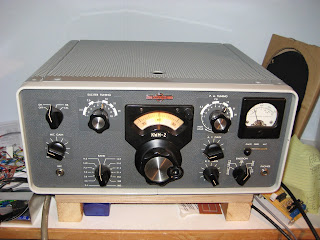
Some initial starting places to look for the culprit. Since it is a SSB issue the 1st look is at something in the microphone circuit. This is where you have to play detective. There is a Mode switch on the KWM-2 that has 5 positions. Starting at the left we have: LOCK, TUNE, LSB, USB and CW .
The Schematic reveals that the 1st microphone stage (of three) has its cathode resistor (180 Ohm) lifted from Ground in the LOCK and TUNE positions and at these same two positions the TONE Oscillator is engaged and an Audio Tone is injected into the 2nd Microphone stage. With the cathode resistor lifted, the 1st Microphone stage is inoperative. So the jump to conclusion idea is that the whole problem is in the 1st stage. Full Tune output because it is out of the loop; but after some time something is heating to make that stage not operate as designed.
That sounds so reasonable only to be wrong. The tube checked good, the voltages and resistance at the tube pins is per the spec and if you sampled the output from the 1st stage using the DSO -- it has consistent output cold or hot. So the problem is elsewhere.
The next question is what else controls the RF Output other than the Microphone Gain Control? Why of course, the ALC circuit. Now in the KWM-1 there is a chassis mounted pot that you can set so that at one end --hardly any output and at the other end the Finals glow RED (an exaggeration). Thus that pot sets a level of RF output.
In the KWM-2 there is an ALC ZERO pot and when the meter is placed in the ALC Position that pot does indeed zero the meter; BUT I see no impact to output as with the KWM-1! A Big Clue here?? In the KWM-2 schematic that pot is connected to the cathode of V4 at one end and at the other end is a 47 Ohm resistor to ground. Logically introducing a negative voltage into the center wiper of the pot would impact the stage gain.
My KWM-2, as built, has a wire from a cable bundle going to the cathode and the 47 Ohm is connected between the Cathode and Ground. So what is factory built is different. However the ALC is more complex that what I have just described. So let is look at some of the pieces.
1. A Sample is taken from the 6CL6 Driver stage
|
|---|
2. That sample goes to 1/2 a 6BN8 (Two diodes to produce a DC Voltage) |
3. Via a Resistor/Capacitor Network the varying DC is fed to V4 and V7 |
4. V4 is only used on Transmit, But V7 on both Receive and Transmit |
Do Not Do This -- but this was a controlled quick test. I set up the KWM-2 and after about 5 minutes and the SSB output was 1/2 I simply pulled the 6BN8 out of its socket and boom full power on SSB. Stop! Next I un soldered the coupling capacitor from the 6CL6 to the 6BN8 and sure enough full output on Tune and SSB. I replaced just that capacitor in hopes that would resolve the matter since it was the 1st link in the chain. It did not fix the problem so more evaluation.
I mentioned a Resistor / Capacitor network connected to the 6BN8, so let talk more in detail about that piece of the puzzle. Coming off of the 2nd Anode on the 6BN8 (Pin 6) are a Resistor/Capacitor in parallel followed in series by another Resistor/Capacitor in parallel connected at the other end to ground.
1. In the LOCK and TUNE Positions Pin 6 is Grounded (No ALC)
|
|---|
2. Connected to Pin 6 is a lead to a Relay Contact that goes to V7 |
3. At the Junction of the sets of Resistors/Caps a lead goes to V4 |
4. Removing the ALC (tube or cap) does what? |
I have some conflicting results that are likely part of the issue resolution just not sure. So here are some considerations. With the cap or tube removed no DC voltage is generated thus no ALC. We see that the SSB operates like it should. But, I also should note that ALC voltage at Pin 6 is different than the ALC voltage as measured in the resistive capacitive network.
In the case of the voltage from Pin 6 that goes to a normally open contact on one of the relays. when applied that ALC feeds a 100K resistor connected to the grid of the 6DC6 which is used both in receive and transmit. When the relay is in the normally closed position then V7 is fed AGC voltage. The two resistors that are in series are a 680K and 1.5M with the series combo being 2.18M. As a voltage divider about 70% of the ALC generated goes to V4.
But another test will cause it to work and this may be another big clue. So, connect back the coupling capacitor and wait about 5 minutes and the 1/2 power condition then ground the connection from the resistor / capacitor network at the junction to the 100K feeding the V4 grid and it works on SSB. So we have an open condition and a grounded condition that makes the circuit work. Noteworthy with the Tube removed or the coupling capacitor open you have no signal on Pin 6 and for V7 when the relay connects the 100K in the grid to the 6DC6 is floating
I availed myself of the experts on the Collins reflector and got some really interesting suggestions. In a thinking out of the box suggestion one responder said 'it is your microphone? When it gets warm the output goes down. Well let's see -- if that were true then how could you get full output by removing the ALC tube, removing the coupling capacitor or shorting out a connection. My test results which were provided in the post did describe the full output conditions. So that is not likely the answer. Next I got an answer back that when you talk into the microphone you will only see maybe 1/4 to 1/2 deflection on the power meter so my rig was working properly. While what was said would be a possibility; but with a two tone test or crudely whistling into the microphone then the meter would indicate the same as the TUNE indications. Another dead end!
Another suggested it was a bad tube and that changing V17 (6BN8) or V4 (6AZ8) is all that was needed. The 6DC6 (V7) was not mentioned. I do have a tube tester and at least 4 replacement tubes for each V17, V4 and V7. They all check good and when cycled through the sockets no change. I did get one email from Germany stating that indeed the ALC likely was the problem.
I am loathe to replace all of the ALC resistors and capacitors (not many and not costly) but it is the access problem that would make it a major undertaking.
So a couple of lessons I learned. Firstly forget the reflectors as a majority of the help was not even germane to the issue. Secondly often the fix involves casting a wide net. I am not there yet; but certainly a better understanding of the KWM-2!
Some comments about other investigative techniques I used. A while back I got a can of circuit freeze for another project which was exhibiting temperature problems. I tried "spritzing" several suspect components once the temperature effect took over. That did not bear any fruit. Dirty relay contacts were also suggested -- so K2 and K4 were shot with De-ox it. No Change.
Eventually something has got to work. We are now at the stage of the problem where we need to take two steps back and go through all of the nuts and bolts to find out what we are missing.
To this I approach I add a recent experience with a KWM-1 which was totally inoperative. I just could not see why it heard nothing not even the crystal calibrator. I happen to have a re purposed tool from those who do jewelry making using colored beads. They use a device that looks like a sewing needle on steroids which also happens to have a neat insulated handle. It is about maybe 4 inches long and just perfect for poking about a chassis. It is great for lifting parts and wires out of the way so you can see what is what.
In the process of doing that on a hot chassis, the tool slipped out of my hand and touched the plate of a 6AL5 Diode. I shuddered as I thought about a huge ball of smoke or perhaps a fire. Well that didn't happen; but the radio started working. It was a miracle! But wait, that plate is not supposed to be grounded so why did it now work? I had an open somewhere. It turns out the RF gain control is run through a relay contact so in Receive it is grounded and in Transmit it is open --NO Receive. I traced the wire to the relay and sure enough in the cable bundle going to the relay, that wire was broken at the pin connection. This was an accidental finding as all of my work up to that point never looked for a broken wire causing an open circuit.
I need to find that analogous BROKEN WIRE in the KWM-2.
12/12/2021 ~ The Broken Wire Journey!
So yesterday I went back to the KWM-2 after it had a time out on the shame shelf. It was early evening and 20M was just about closed down and so I switched over to 40M. Mind you my most recent evaluations were with the KWM-2 only on 20M (of interest with Cycle 25).
So with the KWM-2 into the dummy load I tuned up and got full power output and speaking into the microphone just after tune up -- full power output. I waited about 5 minutes and tried SSB again and Full Power Output. I also checked the meter in the ALC position. On 20M the meter did not move; but on 40 Meters there was significant movement. Could my problem be frequency dependent? I will run more tests today as this could have just been a one off --but if it holds then we are on a different path.
In looking at the schematic when I first started this web page I mentioned that the 6BN8 (V17) was sampling the output of V8 (6CL6) the driver tube. Well the pick up capacitor C157 heads over to that direction but there may be more involved. This might be on the path of the Broken Wire.
C157 it turns out is connected to the junction of two inductors L13 and L14. In turn across these inductors trimmer capacitors are switched across the inductors via switch 6A and 6B. In turn L13 and L14 are part of the Exciter tune mechanism. Other notes to consider, the ALC is shorted by S9E during tune up and so any problem with L13/L14 and the trimmers will only show during SSB.
The ALC sense is more complex than I originally stated. In fact the sensing is done as a part of the PA neutralization scheme as S6A connects to the grids of V9 and V10 and also C184, the PA Neutralization capacitor. Since it is a Collins that is to be expected.
In summary we have some new paths to follow to resolve the problem.
The new paths were followed and it lead to a dead end! In time the 40M drifted down to 1/2 power. So it is clear that it is something in the ALC loop. But at this point a time out.
12/13/2021 ~ Looking for that "One Clue"
Hidden in plain sight might be a great phrase to drag out right now. I am just not seeing it. We have eliminated some things but worth another Check Off the List.
1. Initially I eliminated the 1st Microphone amplifier but maybe another look
2. The ALC looks like "the ripe girl" assuming a re certification of the 1st Microphone stage.
3. The why of the tuned stages for the ALC
4. I found opening or shorting portions of the ALC gives a temporary fix. Logic would say one or the other might do that BUT not both.
5. I am trying to avoid the reflector based on my prior sojourn. but I need a Collins ALC expert.
12/14/2021 ~ A Collins Expert Found
I made another post to the Collins Reflector and got a response from an expert. Why do I consider him that is based on an interaction with individual some 10 years ago when I added SB#8 to my other KWM-2. Significant was that he was able to tell me that my KWM-2 was built in 1963. The Manual I downloaded from the CCA was the 1959 version so there had been some circuit changes -- which I saw in comparing the manual to the as built. That mystery has been solved.
His recommendation was to change the ALC caps as they are "the usual suspects" and replace with mylar and some higher voltage ratings and one case a higher value. Those will be put on order today. Stay tuned.
12/15/2021 ~ Change the Parts!
The Collins expert shared that many of the parts in subsequent product updates were up sized in value and voltage ratings. I was provided an identification list with the new values and these are on order so it maybe this will be a Christmas present. The KWM-2 was in production for a long time (>15 years) so it is obvious many upgrades.
12/16/2021 ~ The Why of Hollow State versus Solid State
While awaiting the treasured new parts to arrive I thought I would share why I seem to move between the two worlds of Hollow State and Solid State.
I could start by being a "smart ass" as my detractors would love to see; but what is true is true and that is simply because I can. First licensed in 1959 I did have solid state experience in projects starting with the CK722 back in 1954. But for the most part the rigs du jour in 1959 were tube rigs --even the Collins gear were TUBES!
But today Hollow State (for the most part and including some hybrids) can be had cheaply as evidenced by my working NCX-5 with a total cash outlay of $63. I got a Hallicrafters SR-160 for $100 and even bought a working NCX-3 for $69 including the NCX-A power supply. Bottom line -- the hollow state rigs can be found for pennies on the dollar. Once you get them up to spec (and let them warm up for an hour) they can provide hours of QSO's with a minimum cash outlay. Many of these were simply dumped on the market because of the shiny new object from ICOM or Yaesu. With a few $$$ in hand, you can catch one.
There are also the benefits of available data and manuals --most for free. There are tons of you tube videos including some tips on how to repair these old "dawgs". Lest I forget there are reflectors and even nets like the Collins, Swan and Drake nets. Out here on the left coast there are many boat anchor swap nets -- so lots of rigs and a resource knowledge base about "who knows what".
Next is the servicing and maintenance. There is an abundance of tube replacements available from real suppliers like Antique Electronic Supply and the Tube Depot. eBay has many sources for tubes but Caveat Emptor -- look at the track record of the suppliers. As for the passive parts -- you can find virtually all of the resistors and caps at suppliers like Digi-Key and Mouser. That said RF Chokes are a bit more difficult. Yet again IF transformers and other inductors are the tough nuts to crack. I have a couple of junker radios where I purchased them solely for the IF transformers and the Inductors.
Accessibility -- firstly you can actually see the parts in these old hollow state rigs and they are color coded or imprinted with their values --READ they are big and identifiable as opposed to 408 sized SMD parts. Now back in the hollow state era -- circuit parts were "stashed" any place there was space.
So while you look at the schematic and see RFC3 --it might be half way across the chassis from where you think it might be. Long ago, in working on a Hallicrafters SR-150 ( a poor man's Collins and superb radio) I was trying to find RFC3 and it was no where to be found until I happened to see a RF Choke soldered to some terminals on the back panel of the chassis -- yes it was wired correctly --that just happened to be an available spot.
Now all would not be kosher if I did not reveal that many of the mechanical parts like brackets and shield box enclosures are unobtainable so you have to know stuff so you can do stuff. On one of my KWM-1's the protective cover over the PA cage was missing. Gulp. The actual opening is a weird shape so trying to use something from a KWM-2 is not feasible. Well detractors I fabricated one out of Stainless Steel purchased on Amazon. I bought a heavy gauge of Steel so that complicated things. BUT I think mine is better that the original OEM part. (Again detractors) I also fabricated the Red Meatball which was missing on the SR-160. You would be hard pressed to see the difference between Factory and N6QW. See below --that is home fabricated!
So the Hollow State in many respects represents challenges beyond our technology driven Solid State Rigs. It is not a case of how to program an Arduino sketch; BUT how do I fabricate a Red Meatball. The challenge part likely is the single biggest driver in working on these old Hollow State rigs.
12/17/2021 ~ Parts Arrived, More Parts on Order.
We all know the drill: we have the hood up and we think this might also be the time to do that other modification. This KWM-2 never had SB-8 installed so I ordered some parts to do that job and they will be here on Monday. When I am done, and if successful, this will be a nice addition to the radio collection. I won't be able to do anything until next week anyway. Life is always interfering with my hobby. BTW I have done SB#8 on the other KWM-2 I have so you might like to see how it is done. BTW -- that was done over 12 years ago. Follow the link.
12/20/2021 ~ All the parts for the ALC and SB#8 are here.
Today I will start with the ALC fix first and then proceed to do SB#8. The actual parts swap does not take a lot of time -- the problem is removing the old parts. A TKT (Tribal Knowledge Trick) involves lining the areas around where parts are to be removed with aluminum foil. This avoids burning near by parts with the soldering iron as the parts are lietrally packed in there like sardines in a can. I learned this trick when I did the 1st SB#8 some 12 yeras ago.
The ALC replacement components were installed including four capacitors and two resistors. The two ressitors were way off -- one designated as 680K actually meausred 1 Meg and the other supposedly 1.5 Megohm measured > 2 Megohm. So that was really significant. The work was done and a test conducted. Nothing changed. So that was not the fix.
But all of the ALC parts were buried in the radio innards and a real bitch to change. Now I am suspicious of the tubes. There are three 6BN8's in the KWM-2 and I moved them around. I found that the output is significantly different with the three tubes. I have two spares and they too result in a low output after a warm up.
Now I ran a test with one of the tubes that I really had a question about. I cut off all of the pins except the two filament pins so that the filament string would be maintained. Full output --although the triode section is in the receive chain so no receive; but again that speaks volumes that the other two tubes in the ALC V(4) and V(7) must be OK as with the heating and just the filament lit on the one 6BN8 -- full output. You are lead to believe the issue is with V(17).
BTW the other KWM-2 which I had in storage seems to have the same issue. Huge clue!!!! So I thought maybe a power supply issue. But I have two supplies. However in moving one of the other 6BN8's to V(17) in the 2nd KWM-2 seems to have long term consistent power output on 80 and 40 -- got late so I will test 20M tomorrow. In the meantime I have ordered up a couple of new 6BN8's from Antique Electronic Supply -- should be here in about two days (just before Christmas). [Update 20M works too!]
While I await the new 6BN8's I am going to do SB#8 on the KWM-2 that never had it changed.
12/22/2021 ~ The Fix Is Holding & SB#8 Installed!
It appears the issue was a marginal 6BN8 tube as I have one good tube from the other KWM-2 and put that tube in either KWM-2 and the radios functions as they should. Have two new tubes coming and if it holds with the new tubes we can declare VICTORY. The Upside Plus: The ALC has been modernized and we have also installed SB-8 in the 2nd KWM-2. It is like night and day. So I am jazzed that one of my prized Collins radios is now working again. With cycle 25 doing well, 20M will see a lot of action from the KWM-2 and N6QW.