The following project was discussed during the September 5, 2020 Virtual GQRP Convention and emphasizes the possibility of homebrewing a working SSB transceiver using a few common components.
Link to a PDF of the slides used in the Presentation
This project uses only 9 Transistors/FET's to make you heard on the airwaves. The lineup includes: Four 2N3904's, Two 2N3906's, Two 2N2219A's and One IRF510. The only IC is an LM386. These can be had for about $5 total. That is a lot of bang for the buck!
[Starting in the upper left corner this is how the rig looked screwed down to the top of the work bench and in the lower right hand corner is the finished rig. The upper right hand photo is a top view of the rig and the lower left hand photo is a shot of the right side vertical board housing the microphone amplifier and audio amplifier stages.]
Suppose you wanted to build a SSB transceiver, firstly to prove you could do it; but most importantly it must not be complex nor should it cost more than two trips to McDonalds for a family of four. The real goal is to have something that is portable, lightweight, small in size puts out 5 watts and can do FT-8 as well as SSB. Read on -- your prayers have been answered! Oh and you would like a choice of band or perhaps two bands.
Let us start first with a block diagram of a proposed project.
As mentioned earlier if you do a device count there are 9 Transistors/FET's all of which are common and the most expensive being a name brand IRF510 that costs about 80 cents. [Name Brand = On-Semi, Fairchild. Forget those 25 cent no name Chinese specials.]
For the Digital VFO, I happened to have used a Arduino Uno R3 that was lying forlorn in the junk box. Long ago I switched over to the Nano or Pro-Mini but still have some Uno's floating around. The ADE-1 Double Balanced Mixer is easily procured as Mouser now sells single units for less than $5 each
As I explained many times over don't even bother with a homebrew crystal filter. Get a commercial crystal filter from either INRAD or the GQRP club. Unless you are very experienced and have some decent test gear building a crystal filter involves a lot more than buying 4 crystals on the same frequency.
Trust me buy the filter. The INRAD Model #351 is about $30 and the GQRP Club has a six pole filter for about the same amount. Forget Homebrew Filters especially if you have never built one nor have the appropriatete test equipment to characterize the filter. You want this project to work and after you have it working then you can dabble with 4 crystals that marginally work alone let alone in a filter.
I intend to provide a detail of the schematics and an overall discussion of the module integration --- but the builder will need to do some of the work. The rig does not build itself.
Here are some construction notes and this is a test to see if homebrewers read the information provided. The stack of emails I routinely receive are moot evidence they do not. The next several bullets test your reading and reasoning ability.
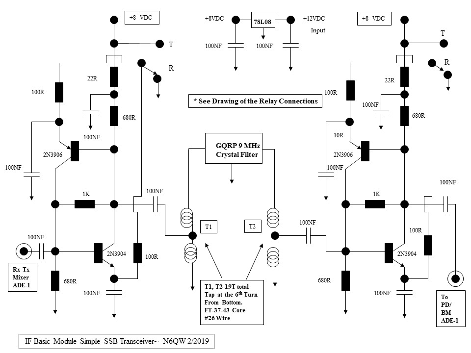
- IF Module Basic and IF Module Board. There are two links below and the first shows the connections of the basic Plessy Amps and the 9 MHz GQRP Club Filter. If you use the INRAD filter the Z in out is 200 Ohms and so T1 and T2 need to be a 4:1 transformer. Wind 6 Bifilar Turns on a FT-37-43 core and connect the center tap to the amplifiers and one end to the filter and the other end to ground. Or fabricate a solenoid winding of 12 Turns with a tap at 6 Turns. For those who will never know 12^2 = 144 and 6^2 = 36. When you do 144/36 = 4 thus a 4:1 transformation. [BTW the inductance of the 12 turns & 6 turns is not so critical as the TURNS ratio. If you were to rigorously calculate the inductances of a 12 Turn winding and 6 Turn winding you would find BOOM the ratio of inductances is still 4:1.] The second link for the IF Module Board shows how the two on board relays are connected and the connections to the ADE-1's. Go back to the IF Module Basic Schematic and look at the relay contacts and this is to understand the science of how the circuit works. On Receive the Emitter resistor (100 Ohms) of the 2N3904 is essentially grounded and the Emitter of the 2N3906 (also 100 Ohms) is also grounded. This is where understanding the difference between NPN and PNP transistors is critical. For an NPN to work as an amplifier the Emitter must be near or at ground potential and the PNP Emitter has to be ABOVE ground potential. Thus with both grounded the 2N3904 is ON and the 2N3906 is OFF. Now in the Transmit condition both Emitters have 8 VDC applied. For the 2N3904 applying 8 VDC through the 100 Ohms back biases the 2N3904 and so it is OFF. But the 2N3906 now has 8 VDC applied through the 100 Ohm Emitter resistor is now in the ON state. Thus in Receive the signal is amplified LEFT to RIGHT and in Transmit the signal is amplified RIGHT to LEFT. Study the Schematic and trace the signals and you will gain a better understanding of PNP and NPN transistors as well as how the circuit can amplify in two directions. Look carefully at the 1K resistor and think about the Base bias on both transistors. This is the science...
- The IF Module Board has the Plessy Amps and the Crystal Filter as well as the two Double Balanced Mixers (ADE-1's) and TWO 12 VDC DPDT relays. It was just convenient to include these two relays on the IF Module Board. The relays are Superglued using Gorilla Glue upside down so that the contacts are like "deadbug". The IF Module Board also has the 8 VDC three terminal regulator. The DPDT relay to the left of the Crystal Filter has one set of contacts switch the Ground / 8 VDC to the two amp stages --just wire the connection point of one amp to the connection point of the second amp. So when this relay is energized both sets of amps are switched from Ground to 8 VDC. The other half of this relay switches 12 VDC between the Audio Amp board on Receive to the Microphone Amp on Transmit. The field coil of this relay is energized through the the PTT circuit. Don't forget the "snubber" diode on the field coil. Now the second DPDT relay on the right side of the Crystal Filter switches the IF connection of the second ADE-1 bewteen the input of the Audio Amp Board to the output of the Microphone Amp Board. The second half of this relay provides power to the 1st relay on Transmit. This second relay is directly connected to the PTT circuit and also controls the final T/R to switch the antenna from the Receiver to the Transmitter. The schematic will make obvious why this was done this way. The 1st relay field coil has one contact connected to ground at all times and this ground connection is the extended to the contact that also supplies ground connection to the Plessy amps. So to engage the 1st relay means you apply 12 VDC to the other field coil contact. In the case of the second relay, 12 VDC is always connetced to one of the field coil contacts and to engage this 2nd relay means grounding through the PTT. Bottom line --it is all about how the relays are triggered to change state. Don't forget the "snubber diode" and I also included a second diode in the actual PTT line so it is only a ground condition to engage the R to T.
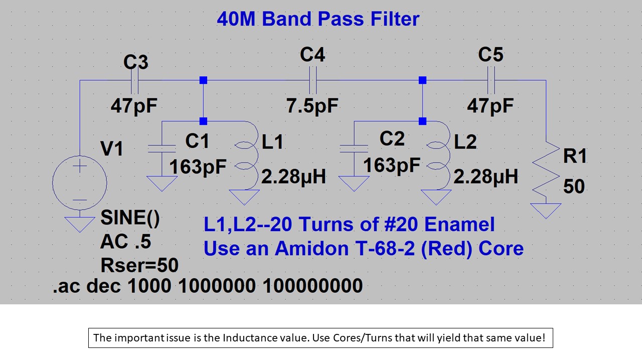
- The Band Pass Filter shows several capacitors like 47PF and 163 PF. I start with four timmers, 9 to 50 PF and these get installed at four locations. For the two trimmers in the tank circuit (163 PF) I simply parallel a 150 PF NPO with each trimmer and then later peak the combo to 163 PF. The 50 PF are simply tuned to 47 PF. Once you get RF into the rig you will be able to peak the trimmers on noise or signals being received. For the interstage coupling, I have a bunch of small NPO caps like 1PF, 2.2 PF, 4.7 PF that I simply parallel to achieve the value needed 2.2 + 4.7 ~ 7 PF.
- For the three inductors in the LPF (2 X 1.34 Uhy and 1 at 1.22 Uhy) the following is the winding info. If you use the RED T-68-2 cores the 1.34 Uhy winding is 15 Turns of # 20 and the 1.22 Uhy is 14 turns of #20. If you use the RED T-37-2 cores then the 1.34 Uhy is 18 Turns of #26 and the 1.22 Uhy is 17 Turns. All other caps are fixed caps comprised of six 330 PF and three 100 PF
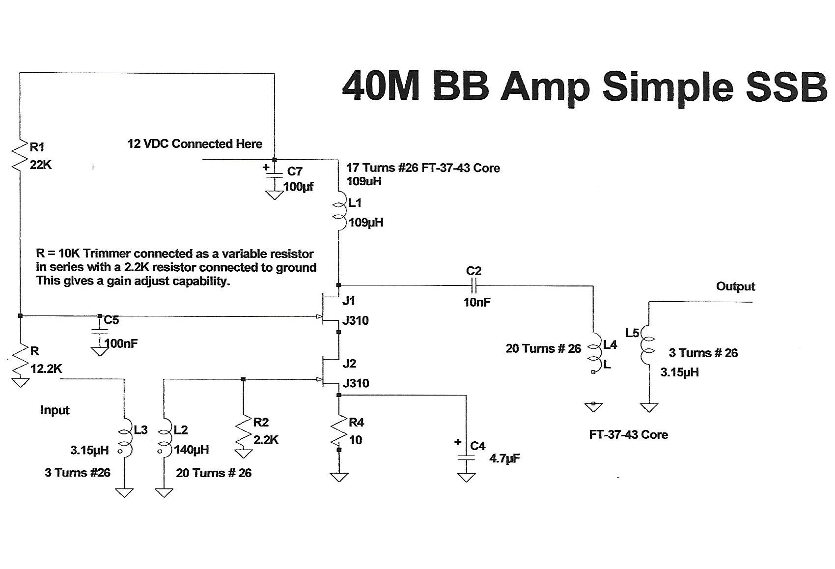
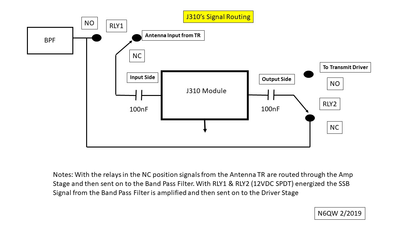
- The J310 Module is rather unique in that two common J310 FET's are connected in a cascade configuration (the Source of one is connected to the Drain of another) so that you have essentially built a Dual Gate MOSFET. The J310 exhibits better overall performance over the 2N3819 although with proper biasing the 2N3819 can work in this circuit. I happen to have found the parameters for the J310. [On my blog n6qw.blogspot.com in the Search box type in LT Spice Libraries. It will find the link to the LT Wiki and then open up the library for the standard jft and copy the data for the J310 and then open up the LT Spice "jft" Library on your computer and paste the info in that library and now you can simulate the J310 all on your own. The J310 is not in the stock LT Spice library.] With the J310 info that amp stage can be simulated in LT Spice and that is the icing on the cake. You can simulate both the J310 and 2N3819 and then decide for yourself. Now the configuration I use includes a gain pot on what is now Gate #2 with the signal applied to Gate #1. My configuration includes matching the input and output to 50 Ohms (just like Hayward) but also includes two small relays. The purpose of these relays is to steer the signals through what I call a single pass amplifier. In essence this single stage on receive takes signals from the antenna T/R relay amplifies those signals and then routes the output to the Band Pass Filter. Through the magic of relay switching on Transmit the SSB signal coming out of the Band Pass Filter passes through the J310's and on to the Driver stage which has also been simulated in LT Spice. This approach saves on parts count and with the manual gain pot which works both on transmit and receive this opens up the possibilities of AGC/ALC control of this stage. BTW this is a test: L4 is grounded although the diagram shows the ground but no connection. I am awaiting to see how many emails I get about a problem with the schematic. READ THE MANUAL!!!!!!!
- Note the J310's were replaced in 2020 with a single 2N2219A. This circuit is the same used for the Driver Stage and thus simplified the parts list of devices. It is relay steered just like the J310's
-
- The IRF510 Linear Amplifier stage comes in may flavors and so you can either use my approach or use what you have found favor with as being "your go to circuit". A couple of notes here about adequate heat sinking. Too often I see a fabrication with a simple TO-220 clip on heat sink --- you might as well use nothing (or to be crass about it, a condom with a hole in it is no condom at all ). I often use the chassis itself as the heat sink and do not forget the insulating kit. Lately I have been following a practice suggested by Allison, KB1BMG and that is to cut off the Drain Pin on the IRF510 since it is so close to the Gate and make the connections to the Tab. I think that is a really good practice.
- The Microphone amp has been simulated in LT Spice and gives a very flat response from below 300 Hertz well beyond the audio range. The Resistor R8 is shown as a 10K resistor for simulation purposes but is a 10K Trimpot located right on the mic amp circuit board. The center wiper of the pot is where the output is fed to the 0.22 ufd cap. The other end of this cap is connected to the relay contact that is only connected to the ADE-1 Product Detector / Balanced Modulator on Transmit. That connection is shown in the IF Module Relay Wiring link. A special note: there is a Low Pass Filter comprised of two 100nF caps and a 1 MHy choke that is permanently connected to the "IF" port on the ADE-1. This is to assure only audio frequencies are taken out of or put into the ADE-1. For those who may be mathematically adept, in the mixing process for receive the output is sum and difference frequencies. The difference frequencies are in the audio range but the sum products are the "RF" at 9 Mhz and the BFO at slightly above or below 9 MHz depending on the BFO setting thus also near 9 MHz and so the sum is 18 MHz +/-. Thus the low pass audio filter only passes the audio (difference frequencies). Now you have just had a science lesson!