A New Transceiver on the Air!
I frequently have several transceivers in work at any one time and eventually some event occurs that causes me to actually finish off one of the rigs. It was really hot on the July 8th weekend in SoCal and so that was the triggering event -- there is just something cool about working in a garage that is running a hot 90 degrees F or for those who use the " other standard " we're talking 32.2 Degrees C.
Here are some highlights of this DifX [Different from a Bitx]:
-
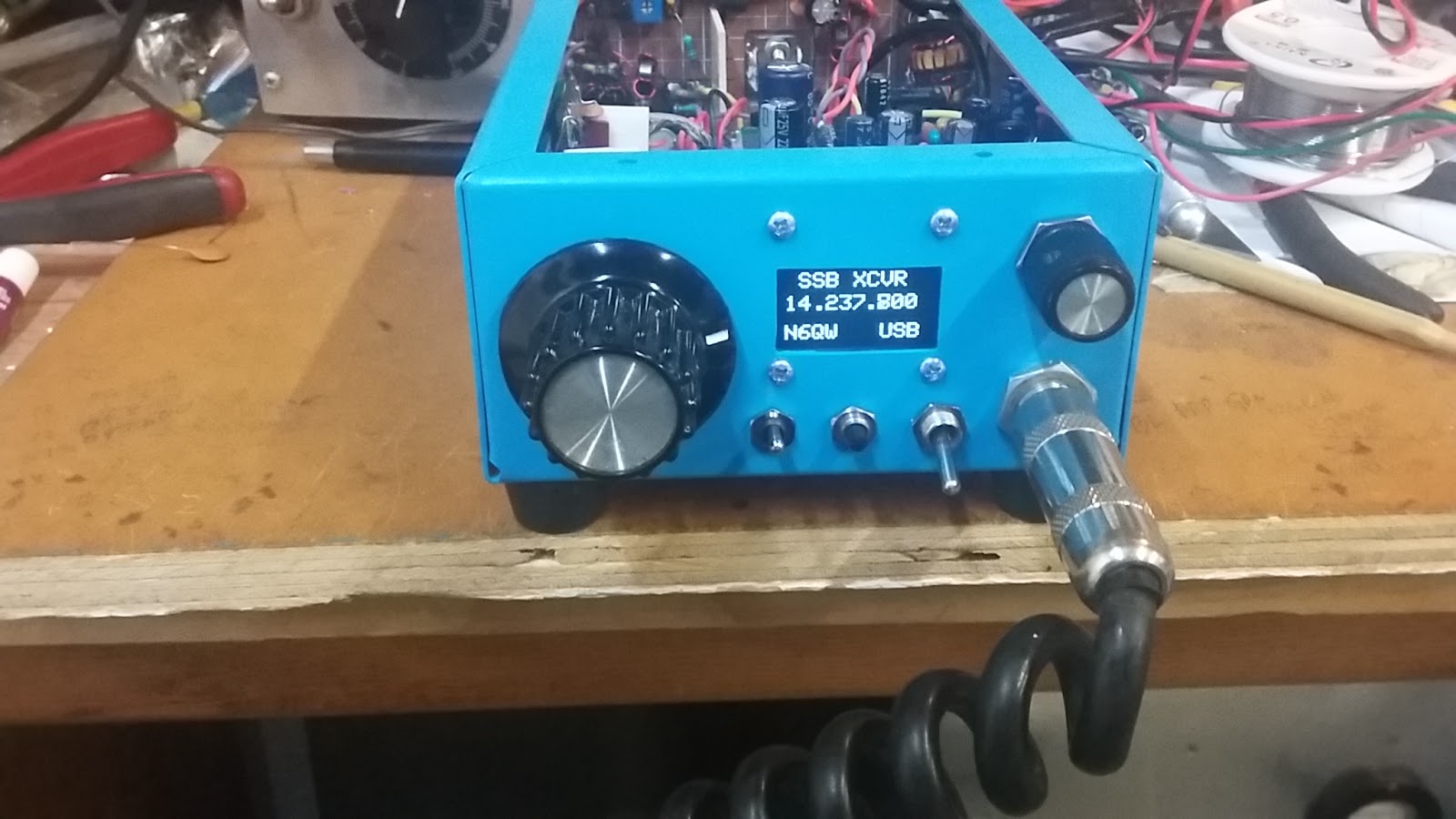
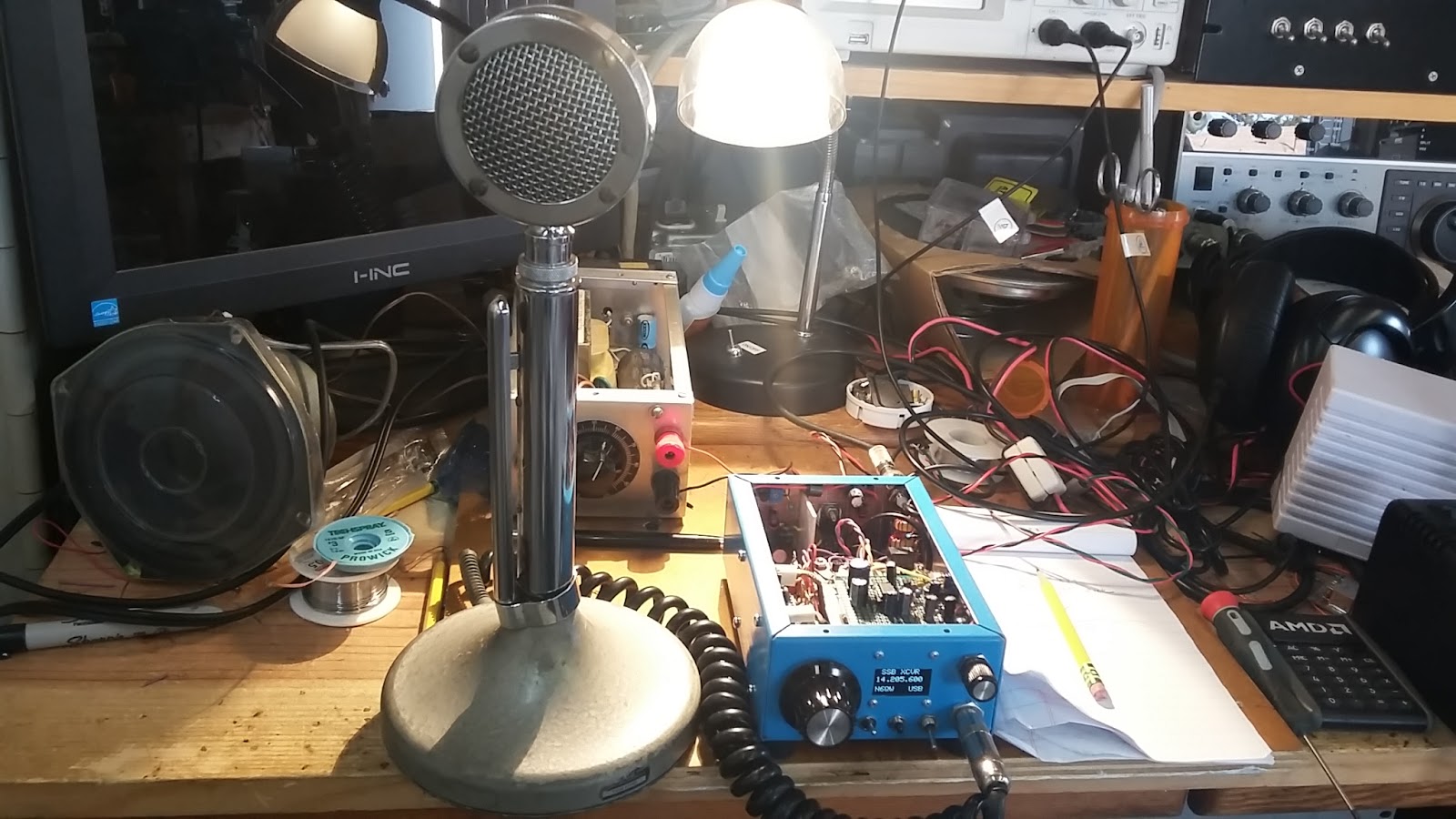
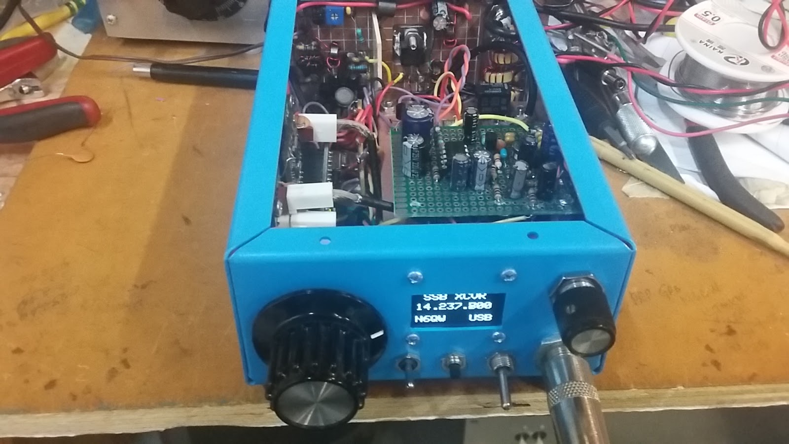
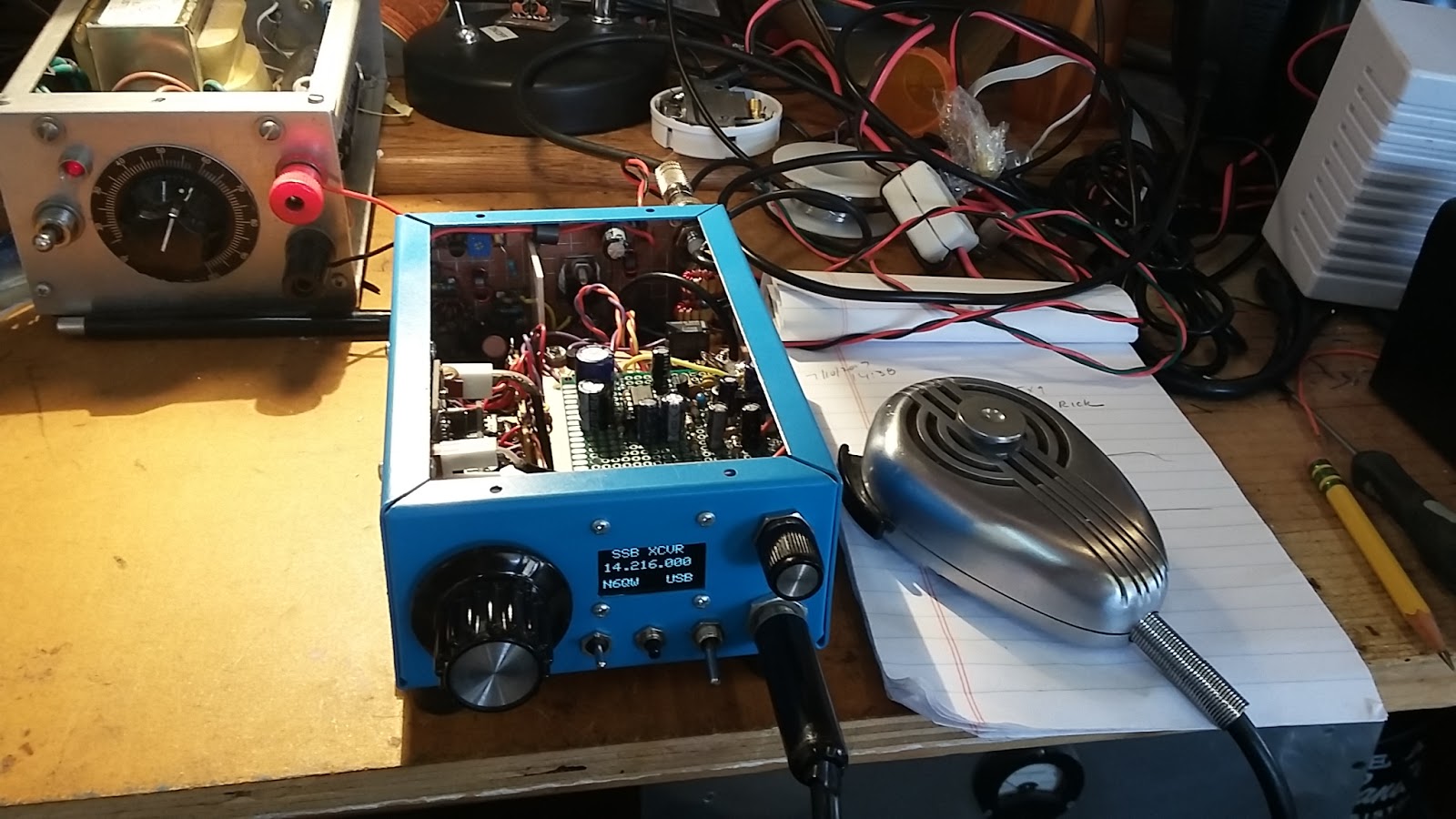
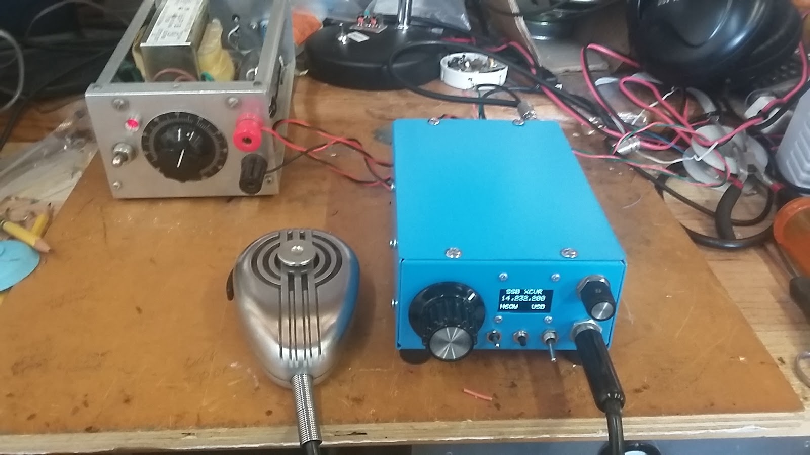
The size is 4X6 by 2 inches high. [For reference purposes the Bitx40 board is 25 square inches not including the display and controls.] I wouldn't call this micro-sized but Mini-Sized is probably OK. A bit of fudging here as I happened to have a 4X6X2 inch aluminum chassis that became the case enclosure. I bought this chassis years ago with the plan for a one "toob" CW transmitter --but who does CW anymore? To get more of a feel of the size of this power house look at the photo below and the relative size as compared to my venerable D-104 Microphone. This says a lot when your rig IS smaller than the Microphone.

-
For the most part the circuits used are ones applied by me in other projects although this is only the third time I have used MMIC amplifiers and seeing how well they work will now become the standard for me.
-
The rig operates on 20 Meters as that seems to offer plenty of activity (even DX) and there are less SDR police and old buzzard nets like on 40 Meters. Yes these are my contemporaries.
-
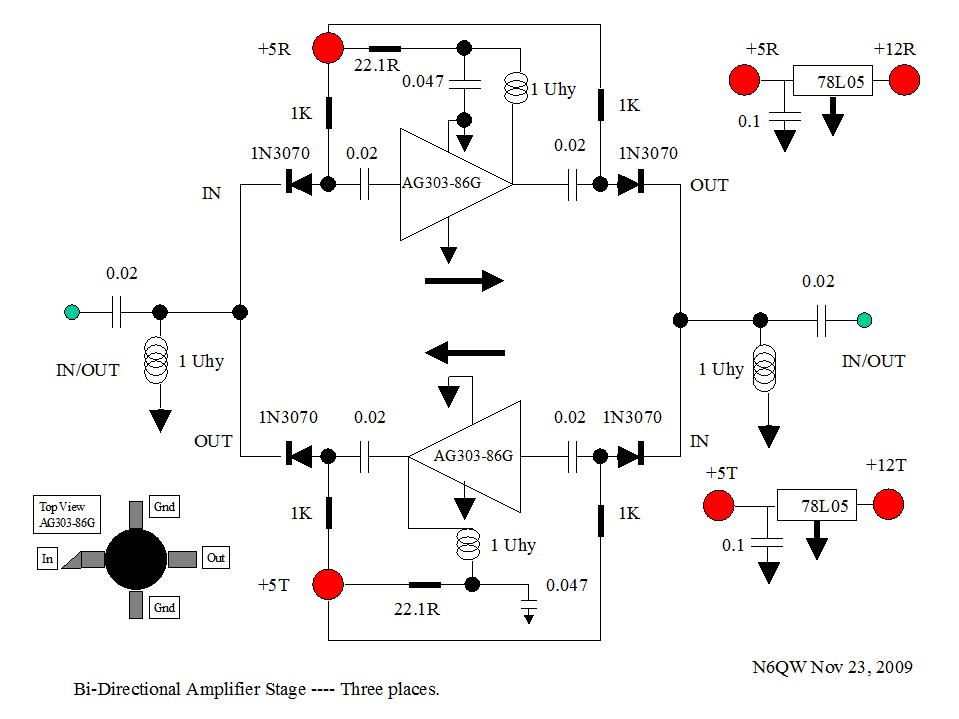
The main IF uses a 9.0 MHz Crystal Filter from INRAD [Model 351] and the Bi-directional amplifiers used for the Rx RF Amp and Tx Pre-driver are two, diode steered and relay switched, AG-303-86G MMIC amplifiers. Going into this stage I used a 2 dB pad and this has really added to the overall stability. Lets face it --these are cramped quarters and lots of potential for unwanted feedback.
-
The Si5351 supplies the LO and BFO and the display is a 1 Inch Square Black and White OLED. Should mention OLED noise has not been a problem. The main Microcontroller is the Arduino Nano. A little detail here is that I provided clearance in the build so that a USB connector can be plugged into this board for any program changes without removing the Nano. A small but very important detail. The default step tuning rate is 100 Hz; but additional selections via the encoder push button are 1 kHz, 10 kHz and 100 kHz. This approach gives plenty of flexibility to tune the entire 20 Meter Band,

-
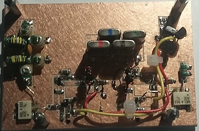
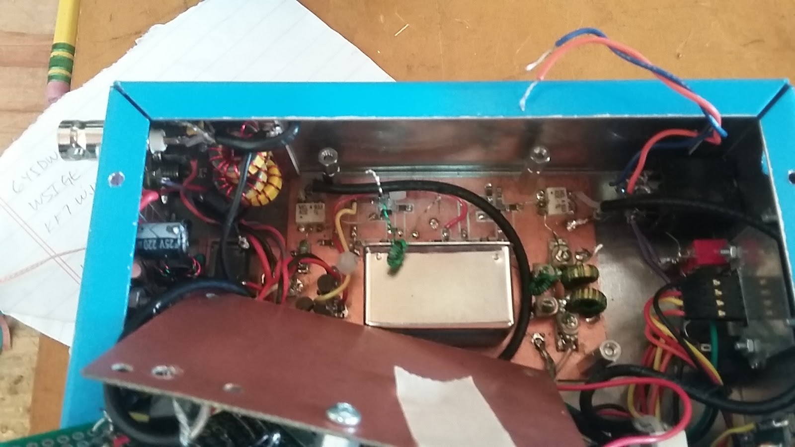
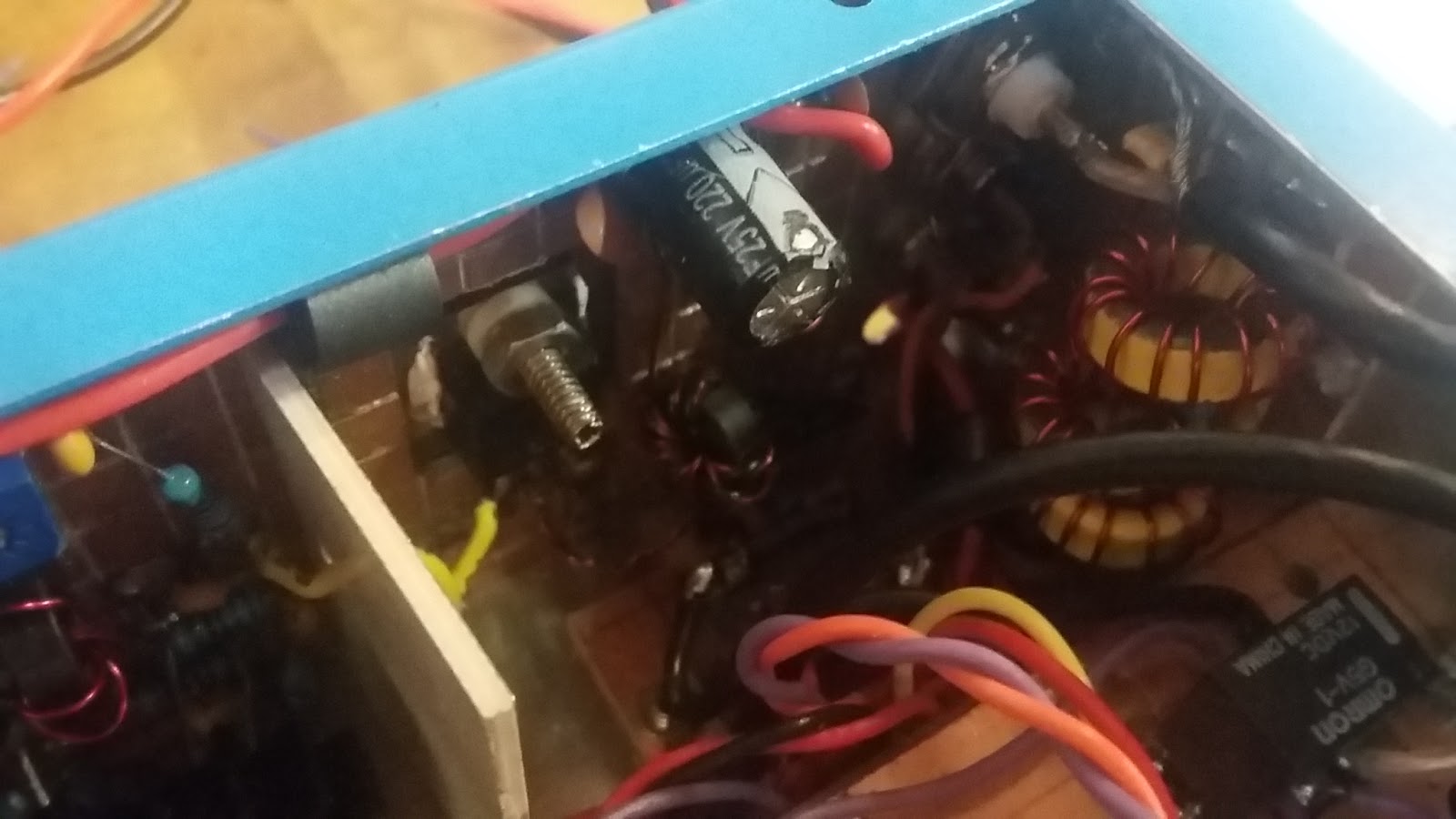
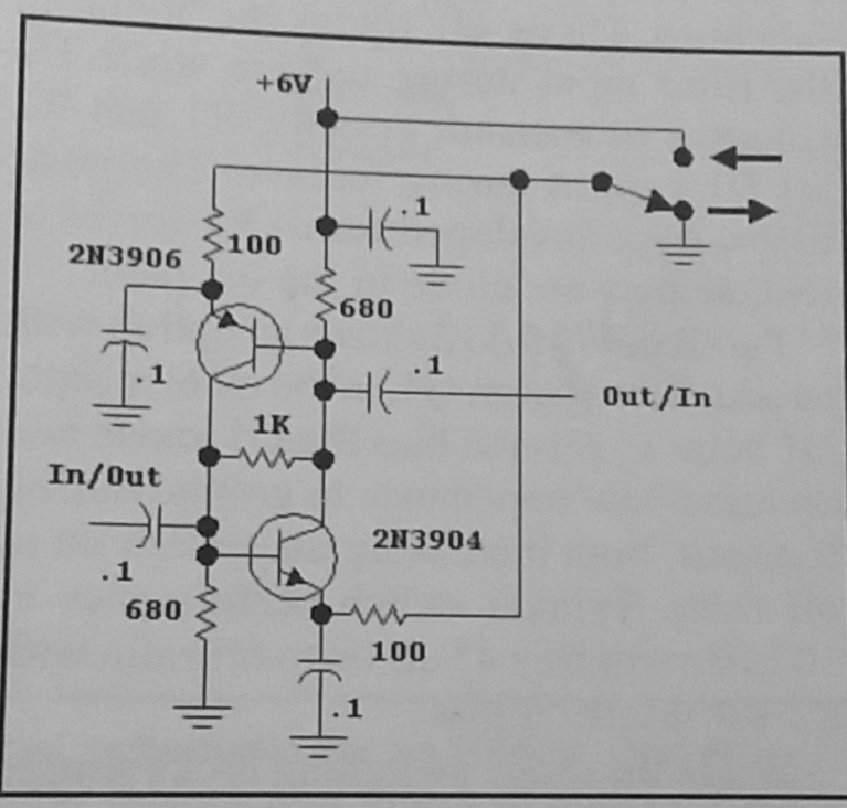
The Bilateral IF Amplifiers are the 2N3904/2N3906 Plessey circuit and the RxTx Mixer is an ADE-1L as is the Product Detector / Balanced Modulator. ADE1-L = 4 dBm devices so set the output on the Si5351 to 2 ma. Note the 2N3904/2N3906 are SMD. The immediate photo below shows the Model #351 4 Pole Crystal Filter which had been in the rig for about a week. On 7/16 I replaced that with the GQRP 6 pole filter. This involved a bit of noodling and modification to the lower board and to the very top board of the three board sandwich. The GQRP Filter being taller than the Model #351, meant I had to add more spacing between the first and second boards. The top board which is the audio and microphone amplifiers had to have two electrolytic capacitors swapped out for shorter ones. In one case a 330 Ufd was replaced with two shorter caps (220 Ufd in parallel with a 100 Ufd). It was a small nightmare but it is all back together and is a testament to a well stocked junk box, fifty years of building experience and throwing caution to the wind. BTW I can tell the difference with the GQRP Filter. Much tighter skirts and actually more output!
-
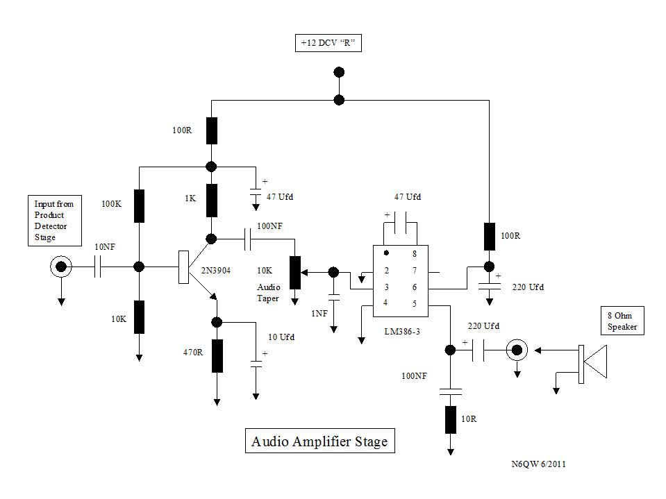
The Audio amp is the LM386 driven by a 2N3904 and the Microphone Amp is a single 2N3904. The RC Shaping filter for the 988 Hz Square Wave Tone coming from the Arduino is also located on this board.
-
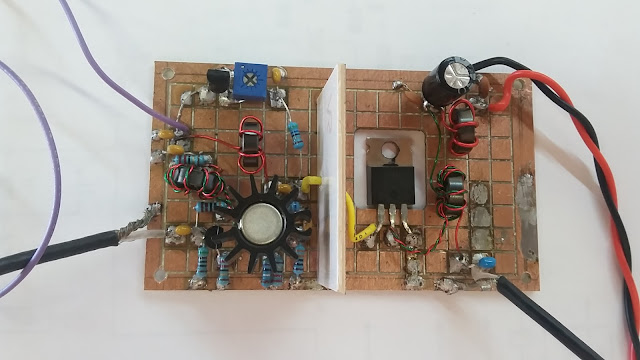
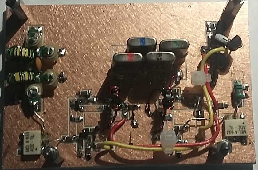
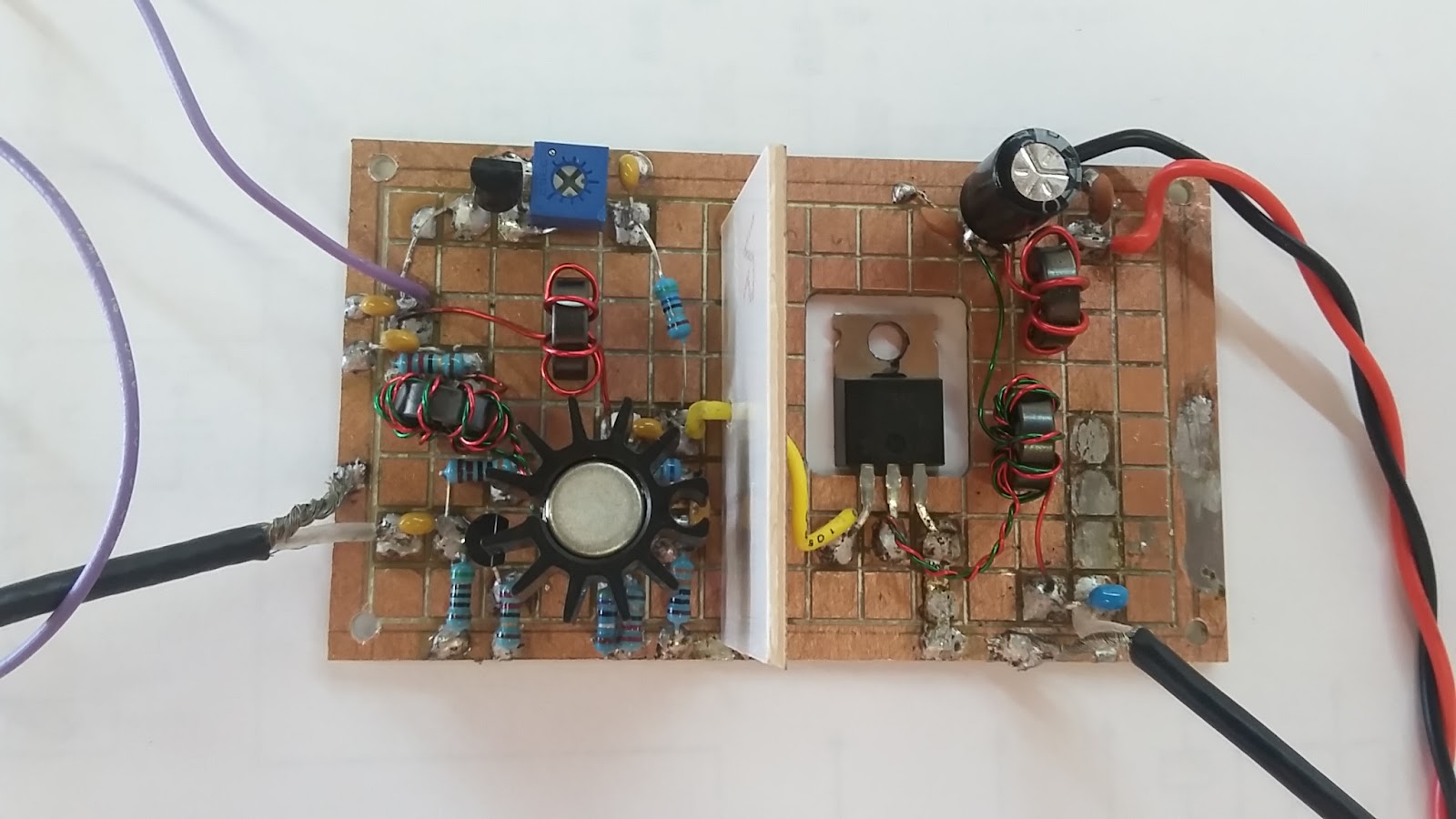
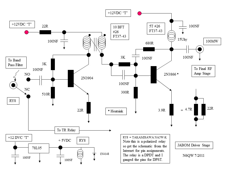
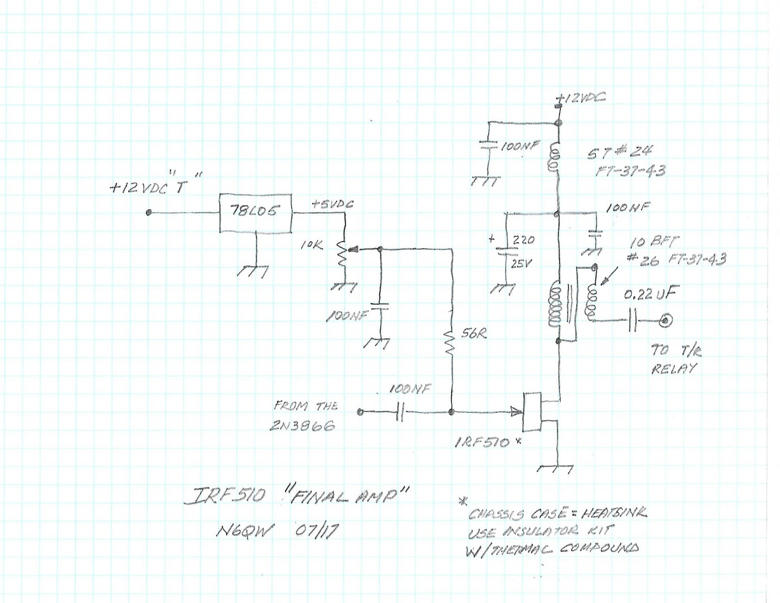
The Power Output is 5 watts via a IRF510 and the driver is the 2N3904/2N3866 standard circuit from EMRFD. This linear amp board is about 3.5 inches long and about 1.9 inches high and fits in the rear of the chassis box. The chassis is the heat sink. Note the shield between the driver and final stage and even the DC bias stage is behind the shield. Some additional bypass caps on the IRF510 have proven to add much to the stability.
-
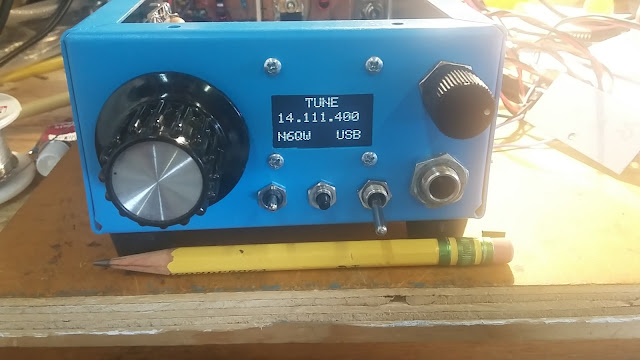
Other features include USB/LSB, MOX and Tune (via a 988 Hz tone generated by the Arduino). I wonder why the Bitx40 aficionados have not added the "Tone Tune Up" to their radios? In time grasshopper, in time. Note on the display the words SSB XCVR --when you place the rig in the Tune mode the wording changes to TUNE and when the timing cycle is over it reverts back to SSB XCVR. There was a bit of trickery to make that happen and not something found on other currently popular radios. Note the size in comparison to the 1/2 used pencil.
-
The paint is standard Juliano Blue.
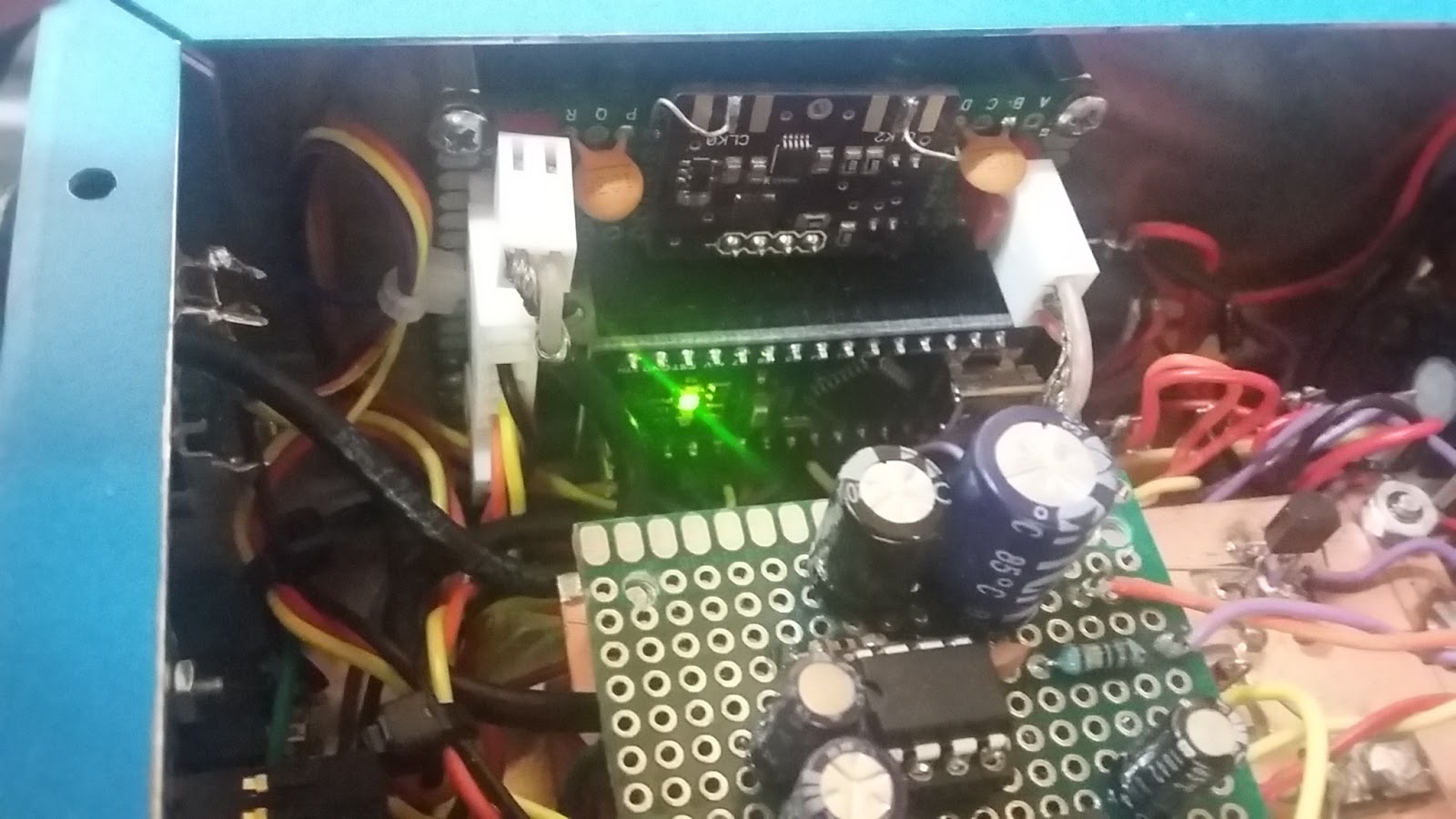

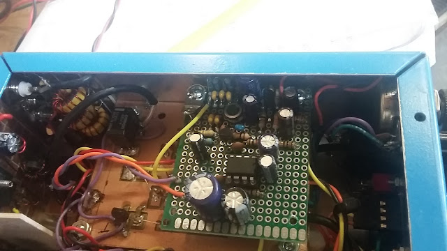
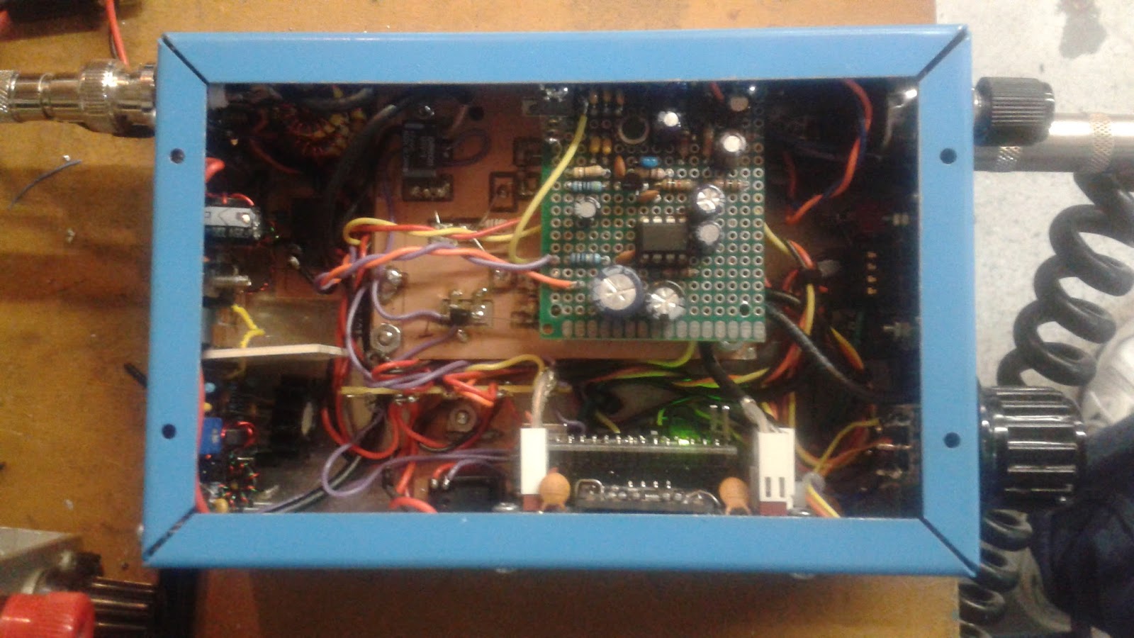
The next photo shows how the board was reworked and move slightly so all would fit back in the case. Note the use of the solder lugs to "collect" the board so it doesn't move and the add of the two smaller electrolytic capacitors so as the assemblies moved upward all of the boards would fit in the case.
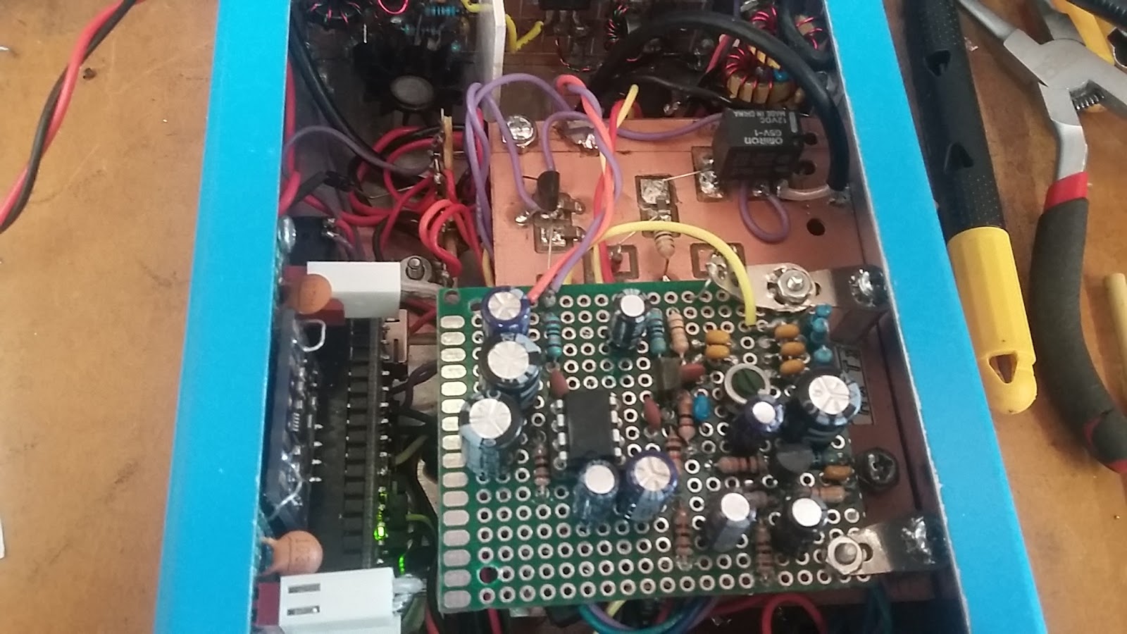
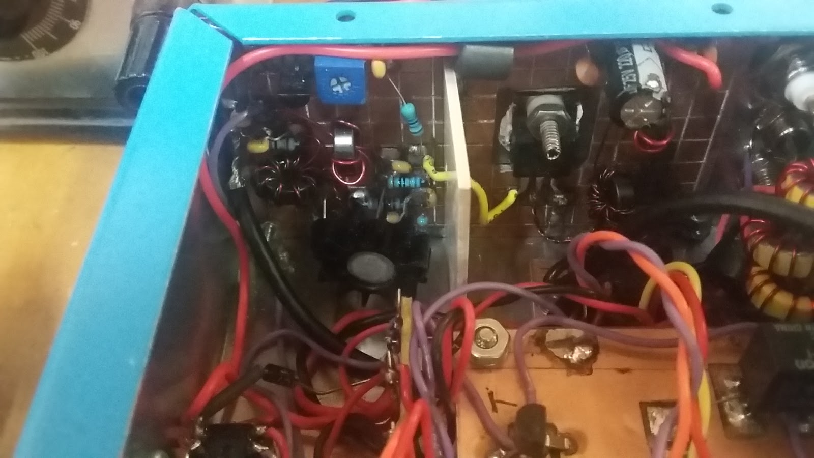

Some construction notes for this project. This is a really compact rig and even the install had to be sequenced so all circuits would fit in the enclosure and could be hooked up. Unless you have experience in building circuits in tight places, it is not recommend you replicate my approach. While the circuit pieces are modular, making them fit was a real challenge. One assembly consists of three stacked circuit boards with the bottom board being the IF, front end Mixer, PD/BM stages and the middle board is the MMIC bi-directional amplifiers and the top board is the Microphone and Audio Amplifier stages. The Driver and Final are on a separate board as is the Arduino. From the photo below you can see it is pretty jam packed into the enclosure.
The OLED noise has not been an issue so check that box. BUT what has been a constant problem is the LEAD FREE SOLDER CRAP. That solder just does not stick and is a particular problem if you are using Manhattan construction. If you are doing ultrasonic wave soldering on 408 sized SMD parts --probably OK but not OK on an IRF510. Initially there was no output from the transmitter --yep a solder connection on the base of the 2N3866 just did not stick. You end up welding the parts and not flowing the solder. This new solder is real crap!!!!!! Mid July I did find some solder containing lead as that is still made in China and available on the Internet
The proof is in the pudding and my new rig just completed its first contact with WA7ND, Rick up in Bend, OR. The report was excellent and I was running the small outboard amp so the Pout was >100 watts. Forget that QRP crap and just move on. I have had a second contact on the rig with KD5CO, Chuck in downtown Texas. I couldn't resist an additional test with the second contact --yep two after burners and the Pout > 600 watts into my two element beam. Now this can be a DX machine. So this is proof that the rig is more than a one hit wonder. On 7/11 I had a really great QSO with Jim, KA5BDO in New Mexico and he was very complimentary of how the rig sounded. He also suggested I use the Turner Dynamic Microphone for rag chews and the D-104 for DX chasing. You can see the new rig with the Turner Dynamic Microphone in the photo below. [That new rig IS small!] Just had a QSO with KH7XS, Bill out in Hawaii running 600 Watts -- another great report. This is a DX Machine in a mere 48 Cubic Inches.
This is one superb rig and lest you forget --it is a DifX! I can't fully express the joy in putting this rig on the air and to have real QSO's with this diminutive sized box. One asks could there be more features? With a bit of more effort on packaging and the add of one DPDT toggle switch, two band operation would be possible. The only adds would be a second Band Pass Filter and a second Low Pass Filter and of course the toggle switch. If I replaced the MOX switch with a band switch then no more panel space would be required. A 40/20 Meter rig would cover the bases or maybe the 20/15 Meter bands or even a 20/10 Meter rig when the sunspots kick back up. Maybe even a 80/15 Meter rig would be your cup of tea. It is merely some code changes to the sketch.
While it may not be possible for readers of this blog to build this project in a very tight space like this 48 cubic inch chassis box -- this is a worthy transceiver project that could be successfully built on an albeit larger scale (or box). That said the smallest SSB transceiver I have ever built was 33.3% the size of this rig --16 cubic inches. Virtually all of the circuits used in the rig have been previously published on this very blog (or articles in QRP Quarterly) so the module schematics are no mystery. If some one would like the Arduino sketch send me an email to the address on my QRZ.com page.
Block Diagram and Some Schematics
The Finished Rig~ Another Successful DifX!
As of 7/15 I have made over a dozen contacts with this DifX rig and am very pleased with the signal reports I have received. Only one negative SDR police report regarding opposite sideband suppression being only 40 dB down. Opposite sideband suppression could be improved with a different filter but a commercial 9.0 MHz Filter I have might not fit in this build.
On 7/16, I did replace the 4 pole filter with the 6 pole GQRP filter so we now have a better filter in the rig. The signal quality is much better on receive and I am sure likewise on transmit. As of July 22nd we have made about 2 dozen contacts, some at 600 Watts, using the SB200 and the most frequenct comment "Your Rig Sounds Great!" This is a DifX in all its glory.
Arduino Sketch Information HERE. This is a text document that can be copied and inserted in a blank Arduino Sketch and then saved as aproject in the Arduino Directory. It was developed using the 1.0.5 IDE and you will also need the graphics and OLED libraries installed in your Arduino Directory in the Library fiolder. If you are not familiar with the Arduino then you must go to the main Arduino site and learn its use.
Other software needed which must be placed in the same folder as the Arduino Sketch. These source files below are text files so each must be first placed in the Arduino IDE and saved with the names shown and as previously directed placed in the skecth folder.
73's
Pete N6QW