Return of the Simpleceiver Plus!
Link to Simpleceiver Sketch in Notepad Arduino Nano IDE 1.0.5
Link
Rotary.Cpp
Rotary.h
si5351.cpp
si53515.h
My Apologies "The Ghost in the Machine" ate the Comments. I have no idea how that happened or how to get them back.
7'3's
Pete N6QW
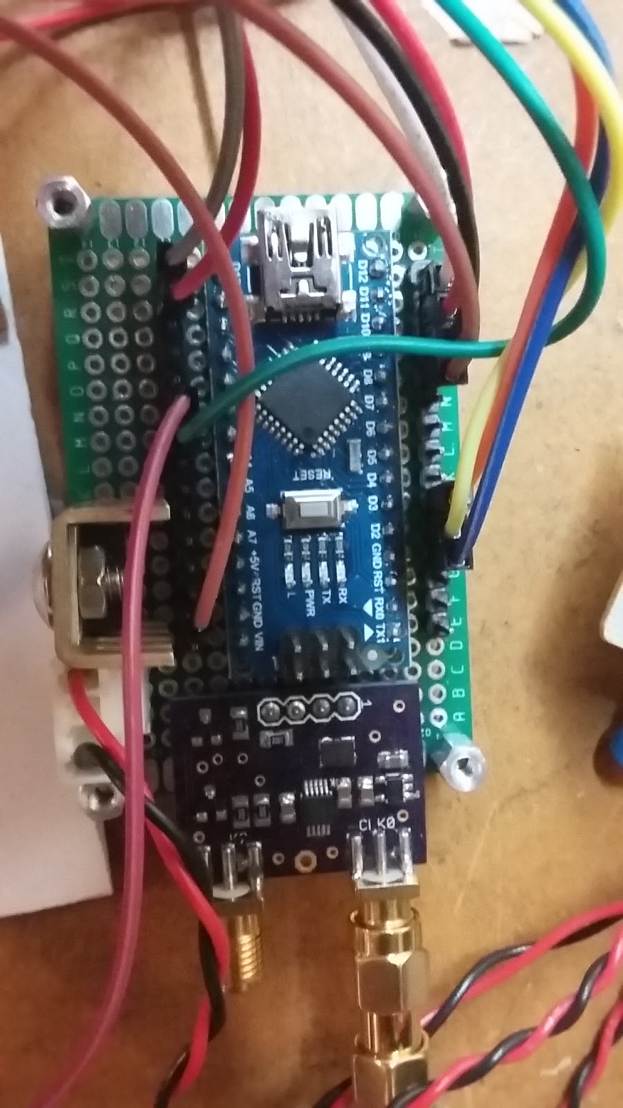
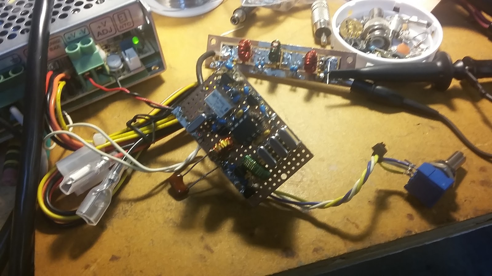
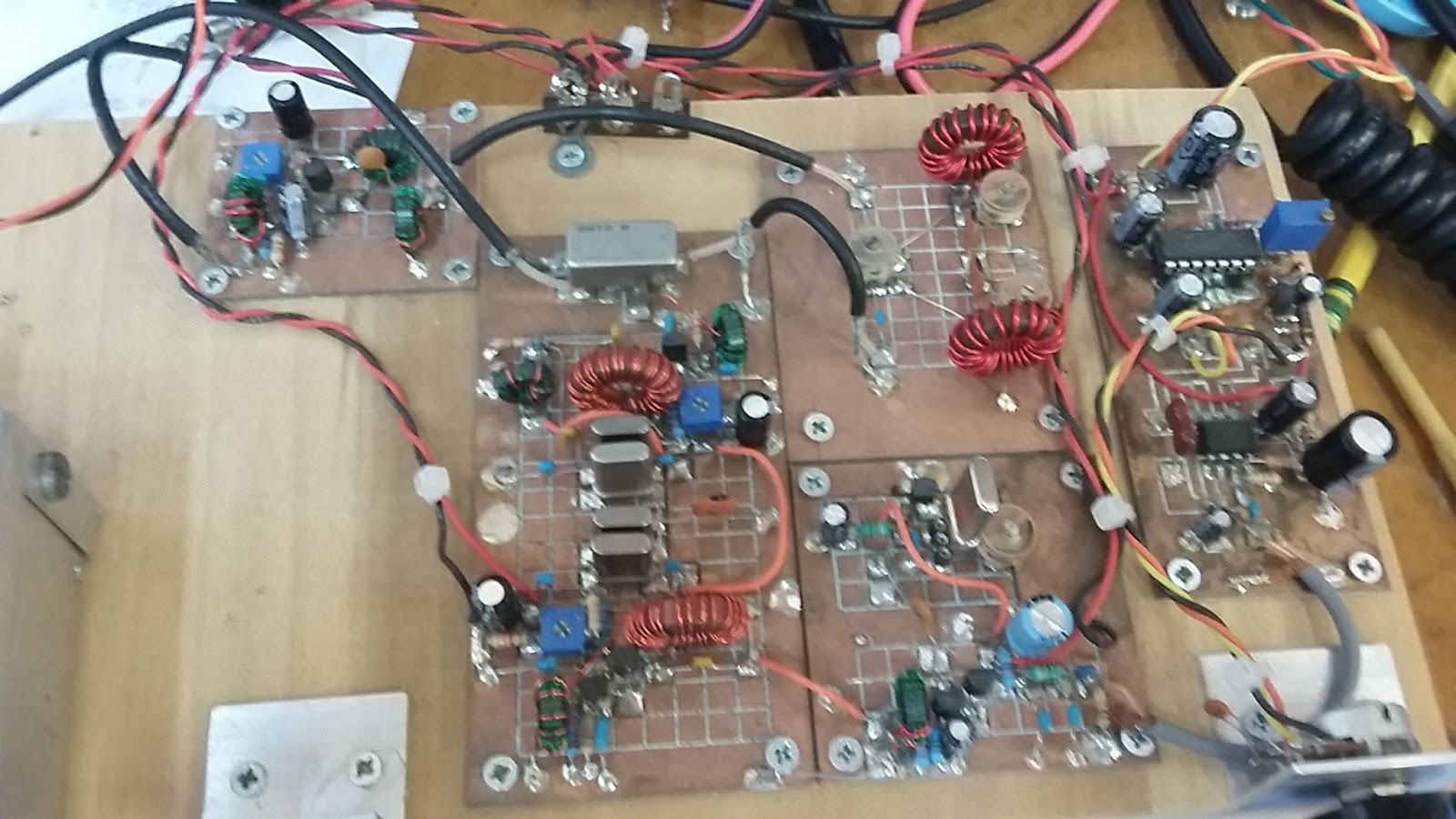
9/08/2017 ~ The Arduino/Si5351/Display Wiring

The above is a pictorial wiring diagram since some homebrewer's are new to schematic drawings. There are many ways to do this and the method I use is to purchase small pieces of prototype board with plated through holes. I insert the Arduino Nano on to a board location and then install pin headers (15 pins each side) and solder the pins at each end to hold them in place. Then using a really ancient technique, I wire wrap connections to the Arduino pins and then solder the #30 Kynar wire to the header pins. Thus from the top of the board there is a header pin connection to each pin on the Arduino.
This method enables wiring changes to the Arduino by simply making a connection to the Pin header. For the Si5351 I solder that to the prototype board and then solder a connection between the Si5351 and the Pin header. Then I use jumper wires to connect to the Pin header to the peripheral devices like the Encoder or Display and the switches. The wire wrap works well as all the signals are digital. That said Coax is a must for connections from the Si5351 to the rig. That is RF my friend.
Those with Eagle Eye's --yes Virginia that is a custom Si5351 Board made by a friend of mine. It has a smaller footprint than the Adadfruit board but is electrically identical.
There may be some really exciting news coming about Arduino/Adadfruit pre-made boards -- stay tuned
73's
Pete N6QW
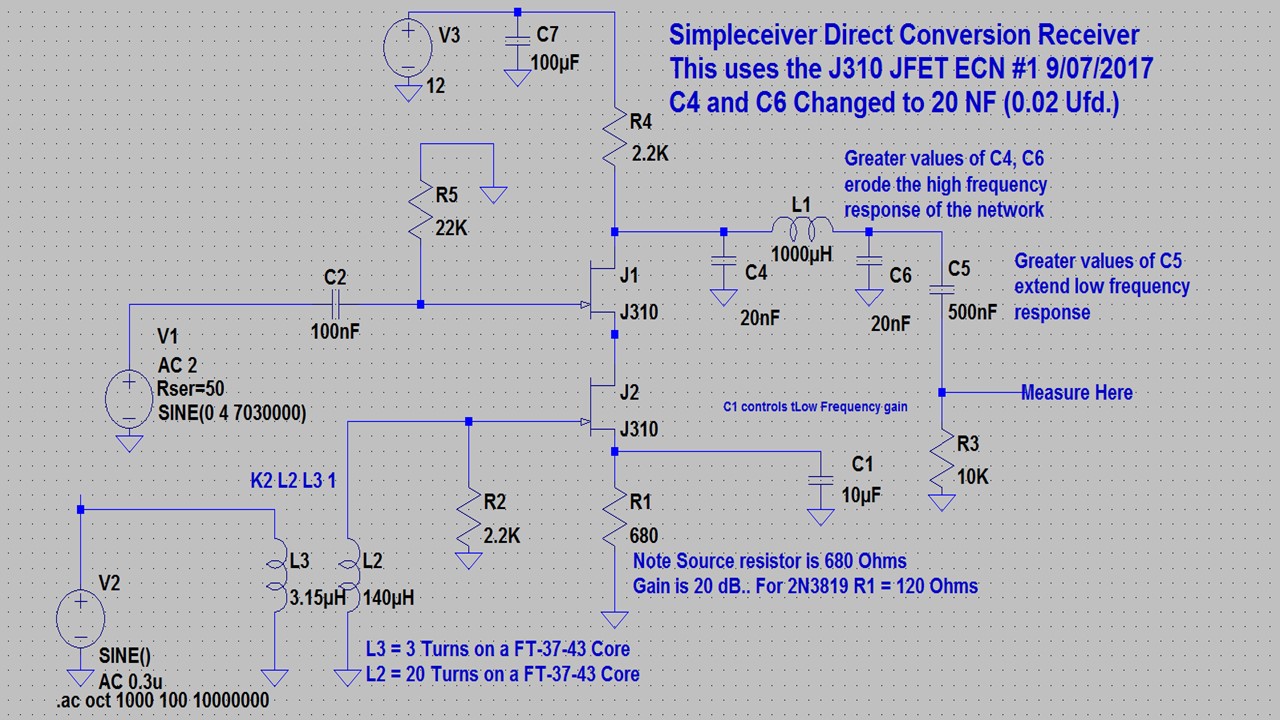
9/07/2017 ~ ECN # 1 (Engineering Change Notice #1)
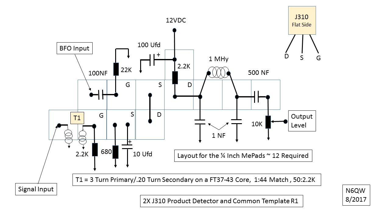
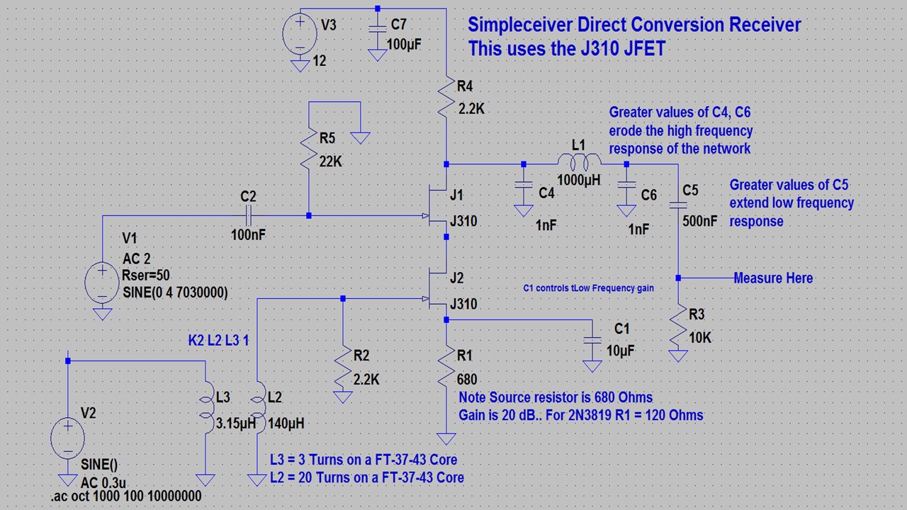
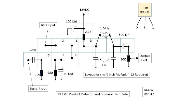
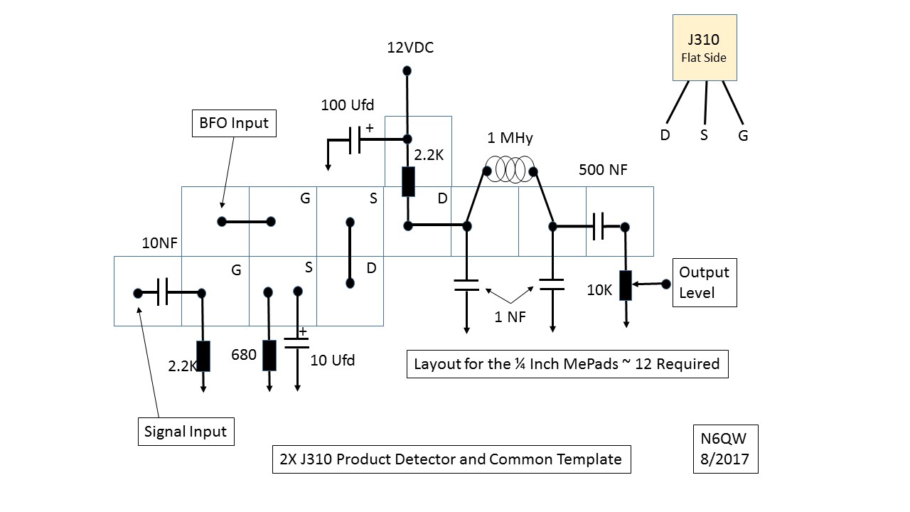
This is a polite way of saying N6QW made an error. In the original Product Detector Schematic posted on this blog the Low Pass Filter had for the values of the LPF Filter Capacitors as being 1 NF. This was discovered by DuWayne KV4QB. I think perhaps when this was designed several years ago I had 10 NF for the values and when I transcribed the info must have dropped the Zero off of the value. With 1 NF the LPF is a very broad LPF. After KV4QB brought it to my attention I went back and looked at the LT Spice model. Actually a better LPF results when you use 20 NF and so an amended model is shown below.
Thanks DuWayne.
73's
Pete N6QW
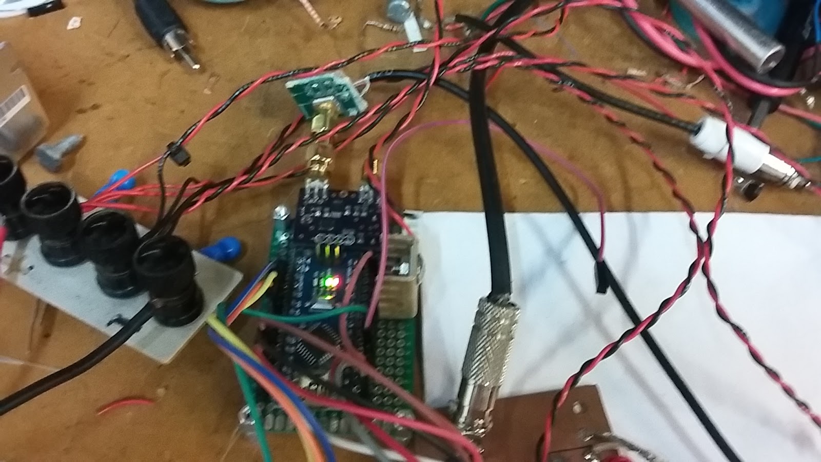
9/06/2017 ~ Building the Digital LO (and BF0)
This is where the fun begins and it began yesterday where with about 5 minutes of programming I created the LO for the Simpleceiver Plus DCR. I am not touting or flaunting my superior programming skills which truth be told I am sorely lacking in having any depth of digital programming abilities. The real impact in what I am saying is that once you have a basic template then it is the changes to adapt an IDE Sketch that can take five minutes.
But our real task is to separate the requirements in the hardware from those associated with the software. Often (like almost daily) I get inquiries about where can I buy this (meaning a whole assembly) with a somewhat naïve assumption that this is "plug and play" and is preprogrammed ready to run. I am not selling such services but there are some pre-packaged hardware kits available but you are still on the hook for the sketch.
Hans Summers G0UPL, a giant in the QRP world sells a hardware kit see www.qrp-labs.com This gets you the hardware and I will be sharing my sketch information on my website http://www.n6qw.con (It is not there yet but give me a couple of days and I will post a note when it is there.)
I will now share how I did the hardware part and basically there are a lot of choice available as to the microcontroller and the display. Basically my approach is "compactness" so I usually don't opt for the Uno R3 or Mega 2560 boards as they are physically too large.
Thus I often look to the Nano or Pro-Mini as the Arduino of choice. The Pro-Mini lacks the USB interface so you must have an external adapter to program the device and it also lacks a 3.3 V on board regulator which is needed for some of the displays. The Nano on the other hand has the USB Interface and the 3.3 VDC port. So I mostly use the Nano. Recently I bought a three board set for $10. Shop Amazon (using the Solder Smoke Portal) or eBay. The Si5351 Boards are being sold by several suppliers (like G0UPL and Adafruit Industries) These boards without connectors cost about $8 and for that you can have three clock output frequencies that are individually programmable.
For a display you have many choices and that selection significantly impacts the code that would need development. Some prefer a simple, clean 1 or 2 line backlit LCD. (A cool blue background with white letters is especially attractive.)
Still others like the Color TFT that comes in various sizes like the 128X128, the 160X128 and even a 320X240. Probably the best among these is the 160X128 as it offers a nice viewing area and up to 256K color choices. But the most important feature is mounting holes. The 128X128 has no mounting holes and the builder is stuck with the problem of how to fasten that jewel to the front panel.
The 320X240 which of course is much bigger does have mounting holes but you must supply an additional piece of hardware called a level shifter as the max inputs to the pins is 3.3 V. The 128X128 and 160X128 can take 5 volts on the pins. Thus the path leads to the 160X128. I have been buying this sized unit from China for about less than $6 shipped to my door.
A whole new class of displays is the OLED [Organic Light Emitting Diode]. These are really small and the photo at the top of the masthead uses the 128X64 with a size about 1 inch by 1 inch. That is small but highly readable. There is even an even smaller OLED that is 1/2 inch by 1 inch that is a 128X32. There are some tricks to keeping noise generated by the OLED's from getting into your rig. One of the downsides of a DCR is the susceptibility to RF noise and AC hum. Thus the OLED may not be a first choice for someone who has not previously dealt with OLED noise.
There are some other considerations that must be put in the mix. The LCD and OLED use the I2C Buss which means only 4 connections (of which only 2 are Analog Pins) whereas the Color TFT use 7 connections (where 6 are digital pins). This only gets to be an issue where other devices configurations use large quantities of digital pins.
A few more bits of hardware are required in addition to the Arduino, Si5351 and the display. These bits include a mechanical encoder, a momentary push button switch (maybe two) and two toggle switches and a few resistors and capacitors. Typically the mechanical encoders come with a momentary push button built into the assembly. A feature of the code is to set a step tuning rate such that you can select a tuning rate from 10 Hz to 1 MHz for each increment of tuning. That is easily handled by successive engagement of this pushbutton where each push selects a different rate. With my fat fingers using the encoder pushbutton usually results in my moving the dial --thus not always smooth.
A separate push button can easily be installed so that step rate change does not involve touching the main tuning dial. The second momentary push button starts the process whereby a 988 Hz pulsed tone is started to provide a tone for Tune Up. One or two other toggle switches can control the selection of USB/LSB and yet another a MOX function.
Thus from the git go the hardware and functionality of the final SSB Transceiver configuration is installed even when being used with the DCR.
When thinking about the software for the DCR I started with the software that will be used for the SSB transceiver and simply set some values to "0" and made no connections to the BFO Port on the Si5351. When we are ready --about 5 minutes with the code and we are there with the software for the SSB Transceiver.
In the next installment I will include a block diagram, wiring matrix and a link to the sketch. But I did want to take some time in discussing the hardware and sketch approach.
73's
Pete N6QW
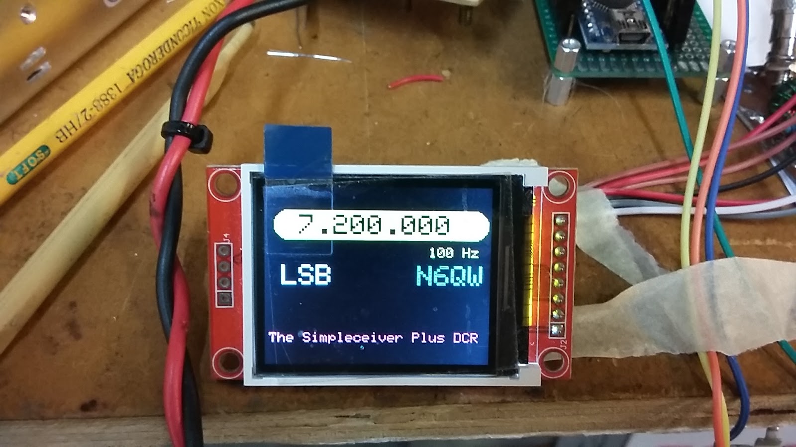
News Flash
The Simpleceiver DCR with the Arduino Nano and Si5351!
9/5/2017 ~ The Impacts of Low Power AKA QRP
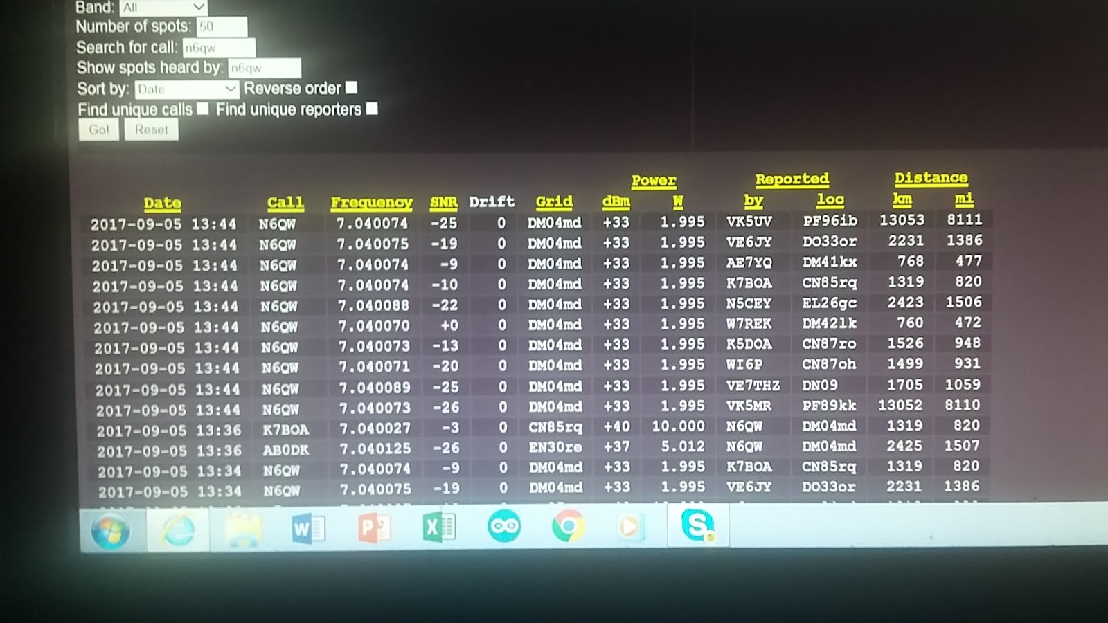
To allay any fears about building the final transceiver project for 40M where the power output is a scant 5 watts, here is a page from today's WSPR log. On and Off I fire up my SoftRock V6.3 where I was running just under two watts; but today was heard by two stations in Australia.
Yes Virginia that was done using my droopy dipole. I didn't just hear stations in VK land -- they heard me! So think about what can be done with 5 watts. I was heard by VK5UV and VK5MR. They are only one mile different in distance so maybe they know each other --But the message here is I was heard 8111 miles away running less than 2 watts.
This is exciting and hang in there as you can soon join in on the fun. BTW I was using the Softrock V6.3 with Power SDR, Win XP Pro on an Intel Atom Machine and my droopy dipole. So nothing real exotic here -- Oh the Sound Card was an M-Audio Delta44. This is old gear but works well.
If you haven't decoded things as yet --WSPR is a good measure of what is happening propagation wise.
73's
Pete N6QW
9/4/2017 ~ Simpleceiver Plus DCR Project Recap.
One of our avid readers suggested I recap the project so that everything is all tied up in a nice bow. So here we go:
-
The Project involves 5 modules: the LO(VFO), RF Amplifier, Band Pass Filter, Product Detector and Audio Amplifier.
-
The RF Amplifier and Product Detector use a common template with a pair of J310's configured as Dual Gate MOSFETs. Speaking of that I ran some LT Spice Simulations with 2N3819's and MPF102. The J310's are the best and the MPF102 are the worst. You can expect to see about 10 dB less gain with the MPF102. So Bite the bullet and get J310's For the total project you will need about 2 dozen (24 pieces). In the RF Amplifier Stage include the 2.2K resistor on the front end (Gate 1) but exclude it on the output. The LT Spice Simulations show two 2.2K's. The second one is not needed. The RF Amplifier stage has matching transformers at both the input and output [3T to 20T and 20T to 3T on the FT37-43 Cores].
-
For the Audio Amplifier Stage, opt for the 2N3904 and LM380 -- no puny audio output here. Since there are not many gain stages in the DCR -- adding gain at the audio level is a good idea. In fact a better idea as the prior stages don't suffer from overload with too much RF gain.
-
Several blog readers (Bob, Greg and DuWayne) have provided artwork/files for boards that can be made for the various modules. I highly encourage their use as these boards resolve some of the layout and feedback problems when a random tack it here solder there approach is used. I looked at the layouts and they are all excellent.
-
I used an Analog VFO and that was for two reasons (The 1st is to prove to N2CQR that I really do know how to construct 1st rate VFO's0 and secondly this VFO while it tunes 7 MHz can swing down to 5 MHz which is the frequency range required when the Superhet version is built since the IF is 12 MHz (12-5 = 7 or 7+5 = 12, the IF).
-
Shortly I will be constructing an LO that uses the Si5351. Since many homebrewers are new to the hobby or are OT's but have not built a lot of rigs, the Analog LO gets you up and running without having to know about Arduino's and Si5351's. Without a doubt the digital side once mastered is like the old adage -- once you try it you will never go back.
-
Take your time and allow lots of time to build each module and resist the temptation to simply add power and let her rip -- most likely you will smoke a lot of parts and burn up the board. Double check your wiring to assure proper and solid connections. Look for shorts and mis- wired circuits. Insure you installed the right part at the right place.
-
Take some photos and lets us share those with the other readers. n6qwham
@gmail.com
9/3/2017 ~ More Board Layout Data/Information
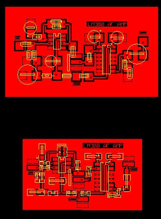
Our friend DuWayne, KV4QB, has been at it again and below is layout for a board that contains the Product Detector and the LM380 Audio Amp. DuWayne's approach is the Toner Transfer Method.
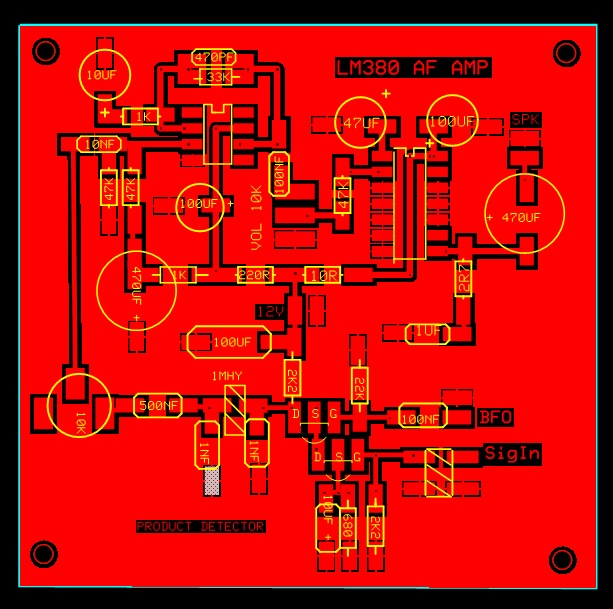 |
| Product Detector and LM380 Audio Amp from KV4QB |
DuWayne KV4QB's Drop Box link can be found here.
If any one has been building the Simpleceiver Plus DCR and would like to share photo please send them to me at n6qwham@gmail.com
73's
Pete N6QW
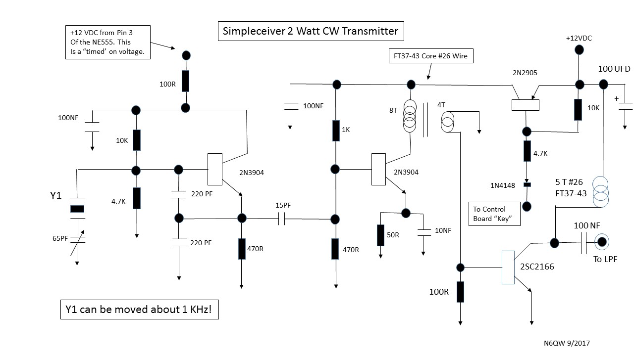
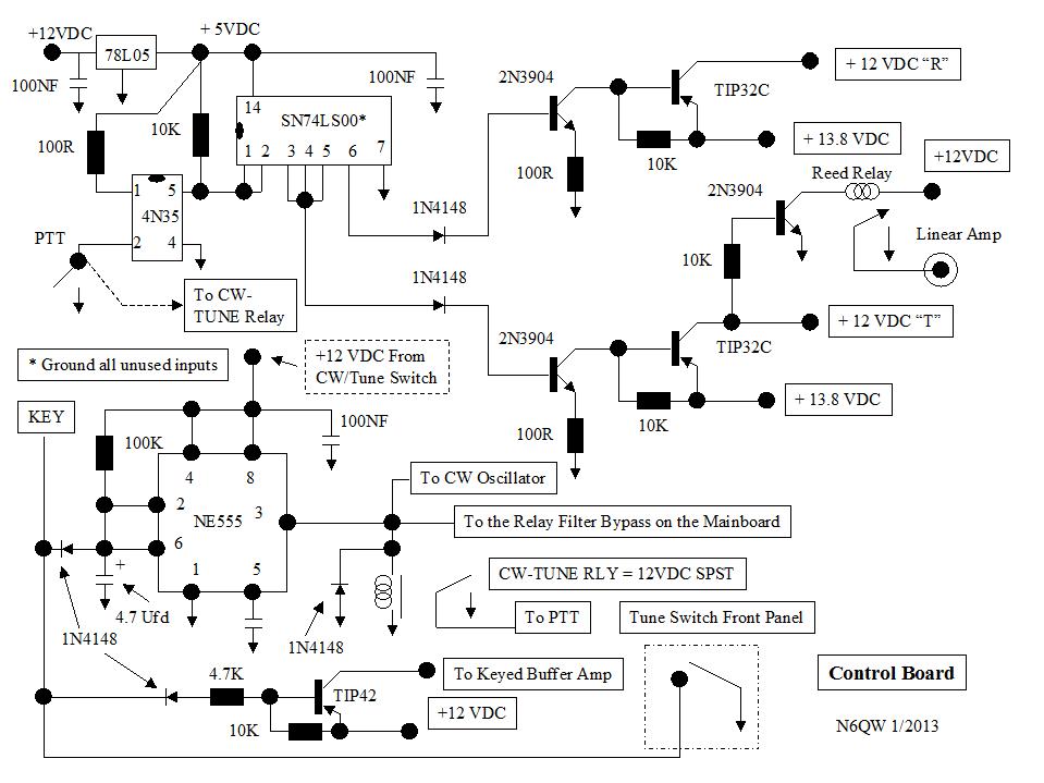
9/1/2017 ~ A 2 Watt CW Transmitter to accompany the Simpleceiver DCR. The Crystal Frequency is 7.030 MHz.

I did listen to the signal on the Reverse Beacon Network and was heard out in Arizona. So now with a bit of antenna switching and adding the special keyer/power module this could be put on the air as a QRP station. I would recommend limiting the VFO to say maybe 100 kHz and then that would give a slower tuning rate.
I plan on recapping the project so far in the next post as the info was provided quickly and not everyone can read my mind. There are some nuances that could be easily missed.
When you hit the key a "timed voltage" is applied to the 2N3904 Oscillator and the buffer is keyed. The final is connected to power at all times. This keying method minimizes key clicks. I did not use an IRF510 but there is no reason why it can't be used.
The Low Pass Filter Constants are taken from the W3NQN publication (QST 1999) which is available on the internet. I am leaving some of the work to the builder!
I can't believe I would even dare suggest the use of CW -- but until the SSB transceiver is built you would have a rig you can put on the air. QRP is QRP; BUT QRP IS NOT exclusively the same as CW!
73's
Pete N6QW
8/31/2017 ~ The RF amp and BPF Board.
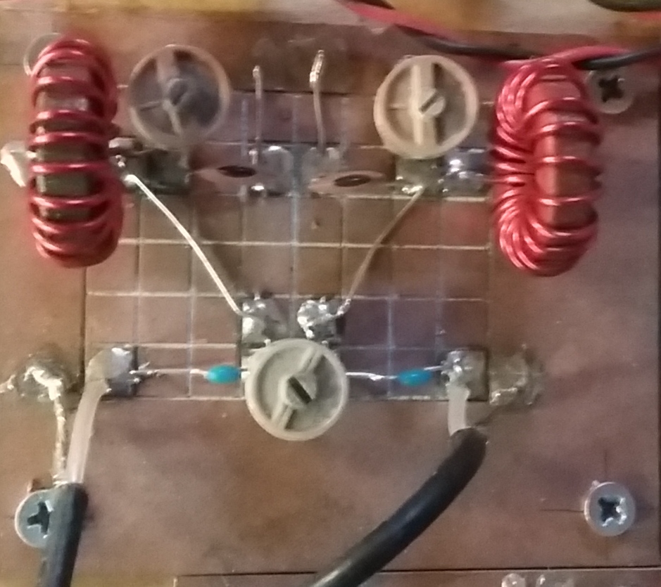
Today we installed the Band Pass Filter on the Board and this now appears to have cleared up the bleed through of the Shortwave AM signals. Nice to see that LT Spice works just not on paper but also in the hardware.
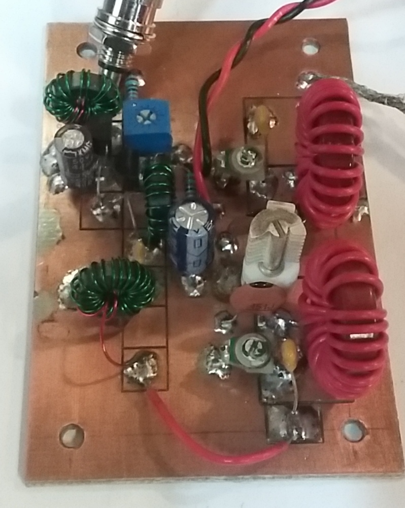
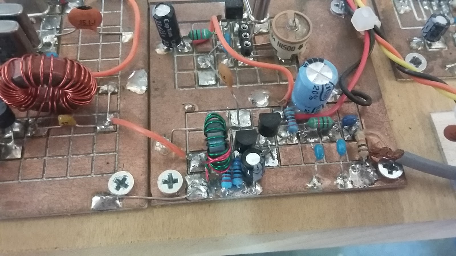
Above is the Simpleceiver Direct Conversion Receiver RF Amplifier (two J310's) and the Band Pass Filter. The BPF has cured the bleed through by the powerful AM shortwave stations operating above and below 7 and above 7.3 MHz.
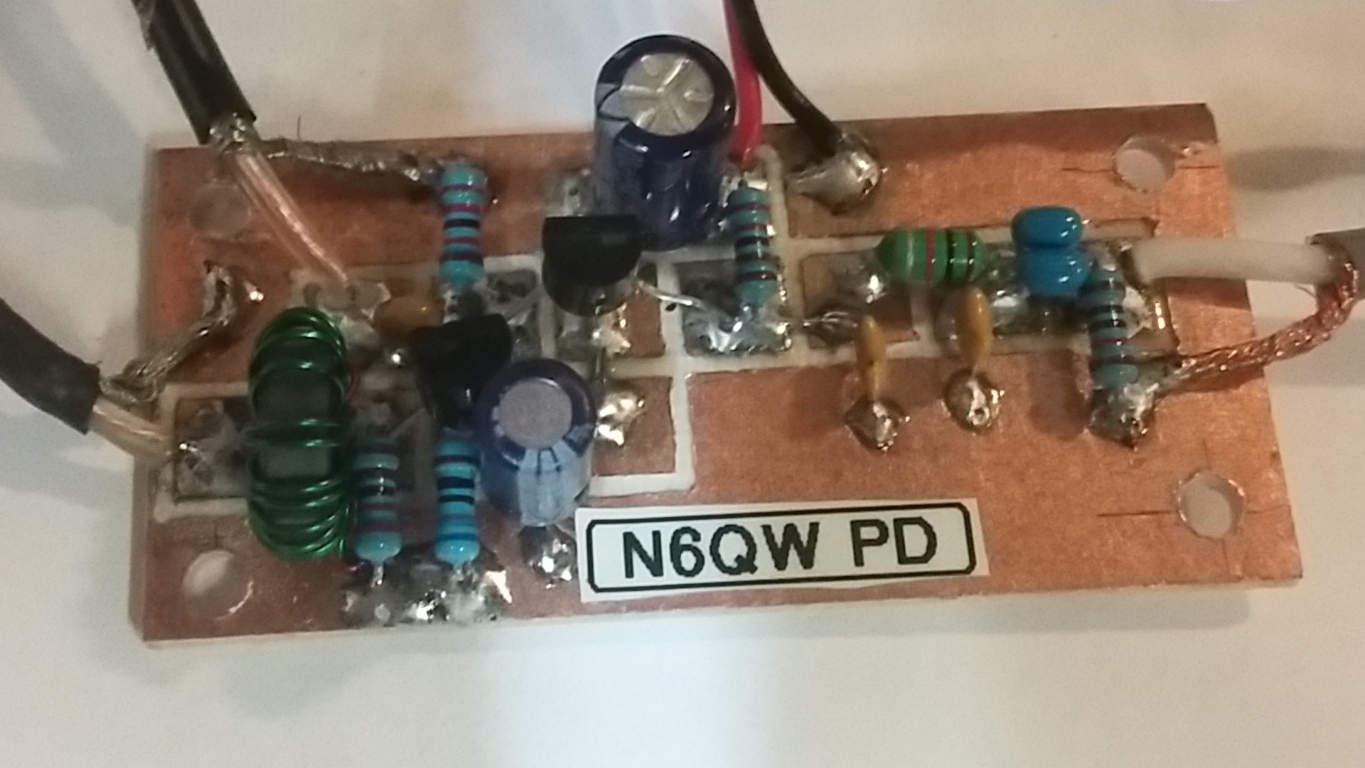
Above is the main Product Detector Board for the Direct Conversion Receiver. The several videos speak for themselves as to how well this performs.
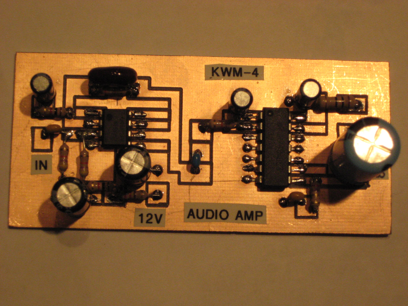
As I mentioned in one of the videos this DCR could be the basis of a simple QRP CW station. I may try to design and build a small 1 watt transmitter that could work with this receiver. Just to make things easy I would use a 7.030 MHz crystal. To make this work I would also build a semi break in keying/voltage switching board similar to what is in the KWM-4. Hit the key and you are on the air.
Not all of this functionality would be required but the NE555 keying circuit would form the basis of the circuit along with the voltage switching. The 4N35, SN74LS00 and switching transistors would be used in the Simpleceiver Transceiver so just being moved forward in the building queue.
73's
Pete N6QW
73's
Pete N6QW
8/30/2017 ~ Adding the J310 RF Amplifier Stage and Band Pass Filter
Yesterday I ran the first tests using a 2N3904 RF amp stage. Today I built the J310 RF amp stage and this short video documents that addition. The board will contain both the RF stage and the Band Pass Filter. I will be adding the BPF once I find my stash of T-68-2 cores.
73's
Pete N6QW
The following video highlights the Simpleceiver Plus DCR CW performance.
8/29/2017 ~ The Simpleceiver is being built!
(New Video from N6QW just added.)
Yesterday I received an email from Walter, AF5WH who is in Texas. First let me say we hope he and his family are safe and that our thoughts and prayers are with those living in Texas. Hopefully the rains will stop and that recovery and rebuilding happens quickly.
Walter shared that he is conducting classes at the Dallas Makerspace and the first project is the Michigan Mighty Mite and right behind that is the Simpleceiver. Walter sent me some photos of his Simpleceiver build which I will now share with you. Noteworthy they are also printing cases using a 3D printer and the color is a close cousin to Juliano Blue.

I see where Walter used one of the suggested techniques involving a piece of PC Board that is "grided" with 1/4 inch squares and then the MePads are glued down to the pads. Noteworthy is that using this method should you want to swap in an LM380 for the LM386 -- pretty easy to do.
I will be anxious to keep in touch with Walter as his classes progress on the project. Thanks Walter for sharing your project. Cool Blue will give it extra MOJO. Walter also mentioned that the building in modules facilitates adding different modules or making changes. Initially to get the rigs working he will use a commercial signal generator as the LO -- then once working a decision will be made as to the type of LO (Analog, VXO, DDS, PLL).
Please feel free to share your builds and I will post photos on the blog.
This morning I haywired in a single 2N3904 RF Amp stage (no Band Pass Filter) and an Analog VFO tuned to 7 MHz. Keep in mind with a DCR you will hear both sidebands as you tune across the dial --thus slow tuning (or build the superhet). I have an Oren Elliot Prodcts 6:1 reduction drive and a big knob. This is a really good reminder why not to build Analog VFO's. This is just a short clip but I will make a lengthy video that will be uploaded to youtube later today. I must now revert to my caregiver life which occupies most of my days.

This morning I haywired in a single 2N3904 RF Amp stage (no Band Pass Filter) and an Analog VFO tuned to 7 MHz. Keep in mind with a DCR you will hear both sidebands as you tune across the dial --thus slow tuning (or build the superhet). I have an Oren Elliot Prodcts 6:1 reduction drive and a big knob. This is a really good reminder why not to build Analog VFO's. This is just a short clip but I will make a lengthy video that will be uploaded to youtube later today. I must now revert to my caregiver life which occupies most of my days.
73's
Pete N6QW
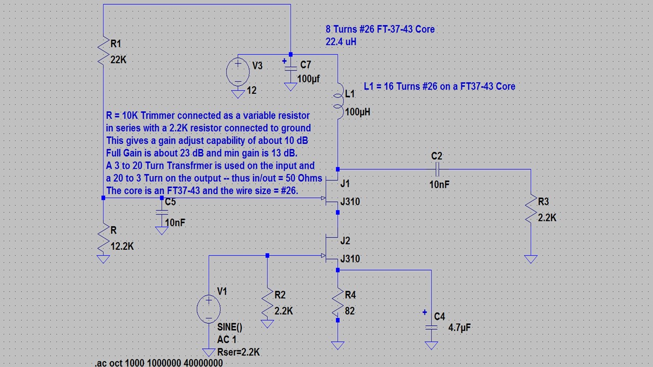
8/27/2017 ~ The Broad Band Amp and the Low Pass Filter
Once again we call upon two J310's to simulate a Dual Gate MOSFET and a configuration similar to the Product Detector follows the theme of the common template.
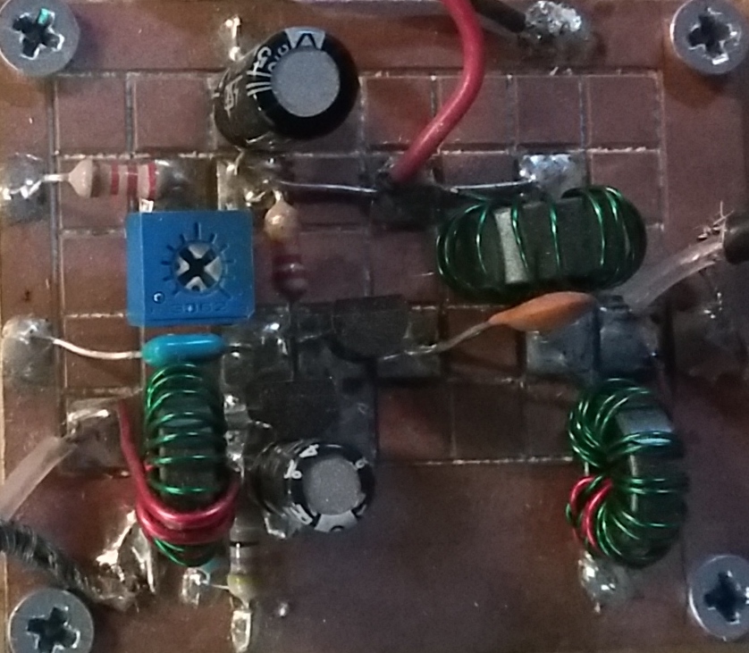
First is the Broad Band Amplifier. The LT Spice simulation shows the configuration without the matching transformers but in the final build these are used as is shown in the photo. A gain plot is also provided:
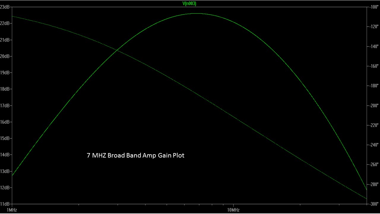
The Band Pass Filter is similarly simulated in LT Spice and the results are shown below.
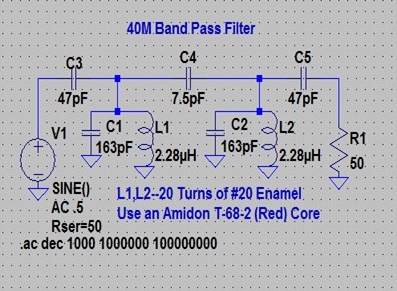
Note the 50 Ohm resistor is not in the final build and is only there for the simulation. The output is connected to the Product Detector and the input connects to the output of the transformer on the RF amplifier stage.
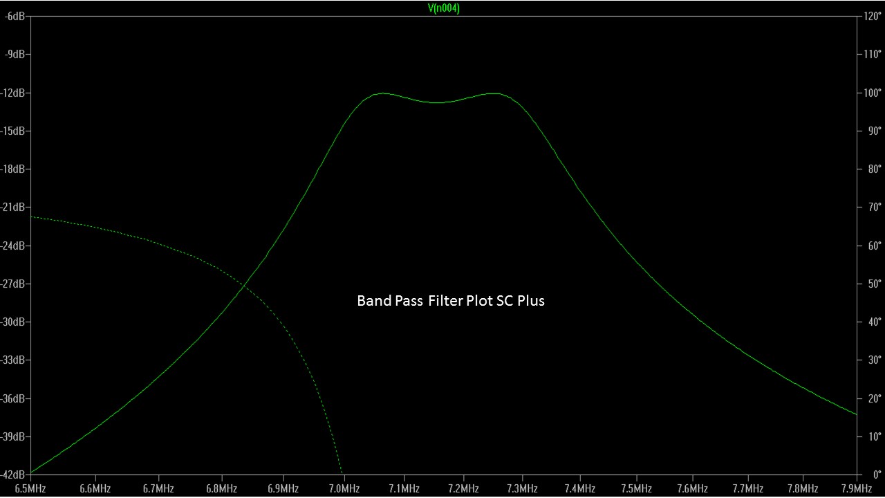
The gain plot above shows a very nice curve that covers the 40 Meter band. The slight dip in the middle is less than 1/2 dB.
Finally here is a photo of the Band Pass Filter. The 163 PF = a combo of a 150 PF NPO and a 15 PF Trimmer.
This now is all of the major pieces for the DCR. In the next post I will quickly recap all of the circuit boards and provide a layout of how to assemble the modules. Yes it will be Al Fresco on a small chunk of plywood.
73's
Pete N6QW
8/26/2017 ~ More on Audio Amplifiers for the Simpleceiver Plus
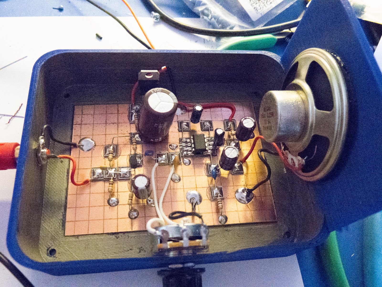
Today I got a chance to wire up the audio amp that I will be using. Actually this is a hybrid of the several designs presented earlier in that the output device is an LM-380N instead of the LM386. The LM-380N is an 8 pin version of the LM380 and with a couple of wiring changes can be used following the 2N3904.
The reason I decided to build the circuit on perfboard was to explore another possibility for the construction. Do Not use the Pad Per Hole perfboard for any RF circuits -- this is audio. Now if you do purchase the Single Sided Copper Vector Board (ouch expensive) that will work FB for RF as the surface is a common copper ground plane.
Now the empty space on the board below the Audio Amp will be used for the single 2N3904 Microphone Amplifier required later in the project.
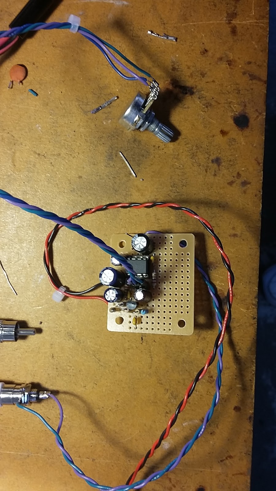
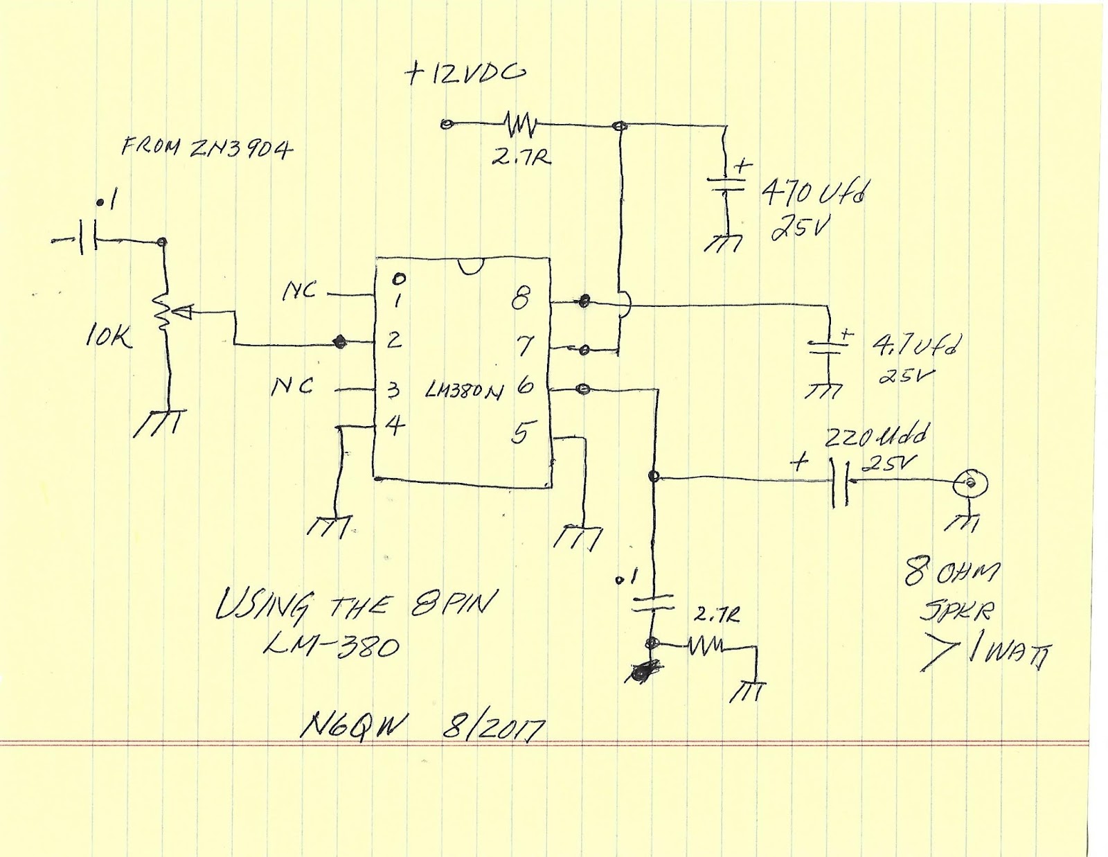
Shown below is the sketch of the circuit using the LM-380N for the output device. Just bought a batch from DigiKey and the cost was around $1.50 each. There are no changes to the 2N3904 circuit and the output is simply fed into Pin 2.Works pretty nicely and output is in excess of 1 watt.
Tomorrow I will post the schematic for the 40M Band Pass Filter and the RF Amplifier stage. Keep soldering.
73's
Pete N6QW
8/25/2017 ~ More Detailed Board Information and Design Data
First Greg and DuWayne have been busy designing Audio Amplifier boards and the links are below. Greg's design is based on KiCAD and DuWayne's is the Toner Transfer method.
Greg's board can be found here:
DuWayne's boards for the NE5534/LM380 version look like this:
DuWaynes' dropbox link is here:
A big Thank You To Bob, Greg and DuWayne.
So what have I been doing? I have collected the parts and made a first run at the Audio Amplifier board parts placement that I will be installing on a small piece of perfboard. But the real effort has been working on the LO for the Direct Conversion Receiver. Since the band of choice is 40 Meters the LO has to be in the frequency range of 7 to 7.3 MHz. This begs the question of how to do this with a method that will give the results without involving and/or the use of exotic processes.
Some of my friends would suggest building an analog VFO, while others might suggest a VXO. While some others would suggest going full throat with the Si5351. For the DCR I am opting to build (or I should say rebuild) a wide range VXO. More correctly a Super VXO which has a wider range that just a simple single crystal VXO.
I tackled a similar problem when I built the 20 Meter Shirt Pocket SSB Transceiver. The resulting circuit was a wide range heterodyne VXO. Basically I built a Super VXO operating at 12.96 MHz. This was done using the crystal oscillator port on the NE602 by connecting three 12.96 MHz Crystals in parallel to that port. The VXO is tuned using a voltage controlled varactor. Separately a simple 2N3904 crystal oscillator provides a signal to the NE602 (Pin 1). I added a small relay that switched two crystals operating around 6.144 MHz. With these two crystals it was possible to tune a large segment of the 20 Meter phone band. With say 4 crystals it might be possible to tune the complete 20 Meter Band. The output is essentially the sum or difference of the VXO and the fixed crystal frequency which was around 19 MHz and the IF was 4.9152. Thus the difference between the LO and the IF is the 20 Meter Band.
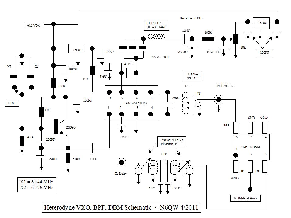
Today I modified this circuit to use 12.096 MHz crystals for the VXO and the fixed frequency is 4.9152 MHz --the difference is 7.180 MHz. Typically the VXO tunes downward from this frequency.
In the test I ran this morning, I was able to tune 130 KHz. Thus it will tune from 7.180 MHz to 7.050 MHz. A fixed frequency crystal say at 4.8 MHz would give tuning from around 7.3 MHz to 7.170 MHz. Some "twizzling" of inductor L1 may enable tuning down a bit lower to cover the 40M CW QRP frequency. I will leave that to the builder.
I padded down the transformer (Pins 4 & 5) by connecting a 470 PF across those two pins so the output would be tuned to the difference frequency (7.0 MHz). That was just a guess but I will finalize the circuit values and share those. I also added a W3NQN low pass filter on this output since you also have sum frequency elements in this output. [The real coil should be 16 turns of #26 on a T-37-2 for the primary and 2 turns for the secondary. Across the primary is a 470 PF Silver Mica cap. The inductance of the coil is 1 Micro-henry and this resonates with the 470 PF at around 7.2 MHz. The new coil is connected across Pins 4 & 5 on the NE602. The LPF is still used and I might need to add a booster amp to get the signal level necessary for the Product Detector. I will know better when all gets connected.]
 |
| Heterodyne Super VXO |
 |
| The Output is at 7.066 MHz |
So this look like a good LO source for the Direct Conversion Receiver. The VXO gives you the flexibility of frequency agility while having the stability of crystal control. Are we getting excited yet???? For full band coverage with a color display you can't beat the Arduino and Si5351!
73's
Pete N6QW
8/24/2017 ~ System Pause
I next will be covering the remaining 3 blocks inclusive of a simple LO, the Band Pass filter and the Receiver RF Amplifier which again employs two J310's configured as a DGM.
But before covering these items I wanted to layout a bit of the additional architecture that will finally get us to a 40M SSB transceiver with an intermediate stop as a superhet receiver. Thus we have DCR > Superhet RCVR> SSB Transceiver. The next posting will detail the three remaining blocks.
Initially I thought about a DSB transceiver but reasoned thinking has suggested that might not be a good plan. Here is why. DSB while it enables phone operation it does take up more spectrum as you have both sidebands present. I also think many DSB rigs result from an inability to execute a SSB transceiver. Once we get the Superhet working --just a few more boards will get us a SSB transceiver.
I do not intend to include CW provisions in the design and there is also a reason for that decision. Aside from the complexity of doing it -- a real competition grade CW transceiver needs a more narrow filter and must also include an offset functionality. I have done in at least one transceiver and that was the KWM-4 as well as a rig designed by W7ZOI -- it was a lot more complex. BUT what I will do is share how it can be done and will leave that up to the individual builder.
My plan is to use diode steering so that in going from receive to transmit, diodes will handle the heavy lifting. A 1N4148 can be had for pennies where as relays would cost several dollars. The plan at this point is to share the crystal filter between the transmitter and receiver. One option was to build two separate filters. It is difficult enough to build one filter let alone two.
The other issue with two filters is that their center frequency undoubtedly will be different. Thus having a BFO work perfectly with the receive filter may in fact be slightly off for the transmit filter. Stop before emailing me! Yes with the Arduino we could generate two different BFO frequencies but then we would have to compensate the "actual frequency display" so it reads the same on both transmit and receive. It can be done -- but easier to just share the filter. That also means two additional IF amps going in the reverse direction -- but not difficult to do.
We will have another decision point in the SSB Transceiver variant with regard to the product detector and balanced modulator. We either need to build a second product detector to make it operate as a balanced modulator or get a double balanced mixer device and just use that for both functions. Cost is an issue -- the ADE-1 when bought in quantity can be had for $4. A separate PD and BM using the J310's may cost a bit more than $4. Lots of trade-offs. The front end will use a packaged DBM so the Mixer stage is both a Receiver and Transmitter mixer --that is why the Band Pass filter is where it is.
I am bringing this subject up for two reasons with the first being what an engineer must do when designing a rig. What are the performance trades versus the cost trades? Secondly there may be practical reasons such as the rig becoming so big with literally hundreds of circuit boards. Nothing is in stone but I thought this was an appropriate time to bring this up.
Still hope to get the audio amp built --unfortunately Life has gotten in the way of my projects. The XYL is not in the best of health and so the last several days were taken up with medical appointments. I do think we are now on the upside and so I can get back to the bench.
73's
Pete N6QW
8/23/2017 ~ Audio Amplifier Time. (With some new info.)
Added ExpressPCB Manhattan layout for the 2N3904/LM386 Amp. Many Thanks to Bob N7SUR
There is a fundamental problem here -- I know where I am going but the readers are probably scratching their heads (much like the aftermath of the event in Phoenix, Arizona yesterday) --where is this going? Trust me --I do know where I am headed!
Lest I forget let us begin with a block diagram of the Direct Conversion Receiver and then it may be somewhat clear the why of starting with the Audio Amplifier. Note I have also included the impedance matching goals which will become even more important as the project morphs into a transceiver.
The first question that should pop up is why is the RF Amplifier ahead of the Band Pass Filter as many will say intuitively these should be reversed -- patience grasshopper. Please resist sending me a blistering email! There is a good reason for this and that is answered when the transmit functionality is added.
I am starting the project with the audio amplifier as it is "my process". You can start wherever you want; but by starting from the back end and working forward, each piece that is added becomes a part of the test system. The block diagram reflects this test system approach. Get the audio amp working with sound coming out of the speaker and then you can cross that off the list and just move forward from there. The LO can be something as simple as a 7.030 MHz crystal oscillator and that will let you test the Product Detector. Higher up the pole is of course the Arduino/Si5351 --more on that in future posts. But for right now we will start with the Audio Amplifier!
Long standing I have a thing for not building the discrete part audio amp as it uses too many parts, usually results in wiring errors and gives only marginal performance. You are welcome to use anything that you prefer but you are on your own if it is something other than the two suggested circuits.
The first circuit shown below is one of the pre-amp stages and this has been simulated in LT Spice. Convince yourself by actually using the software and look at the results. I strongly recommend that builders do this simulation to learn the power of LT Spice.
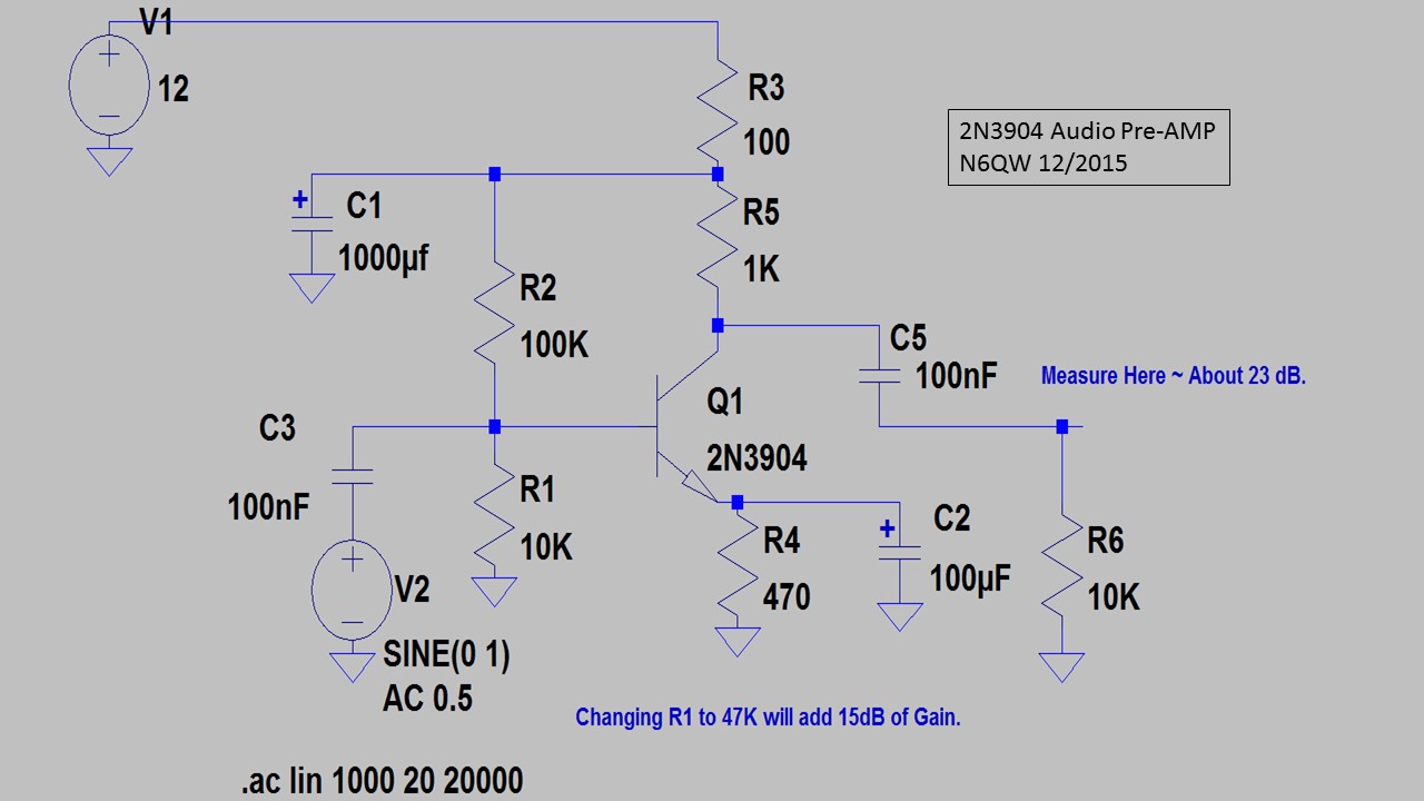
The Upper Plot Shows the Gain is Flat over the Audio Range.
Added Manhattan Layout
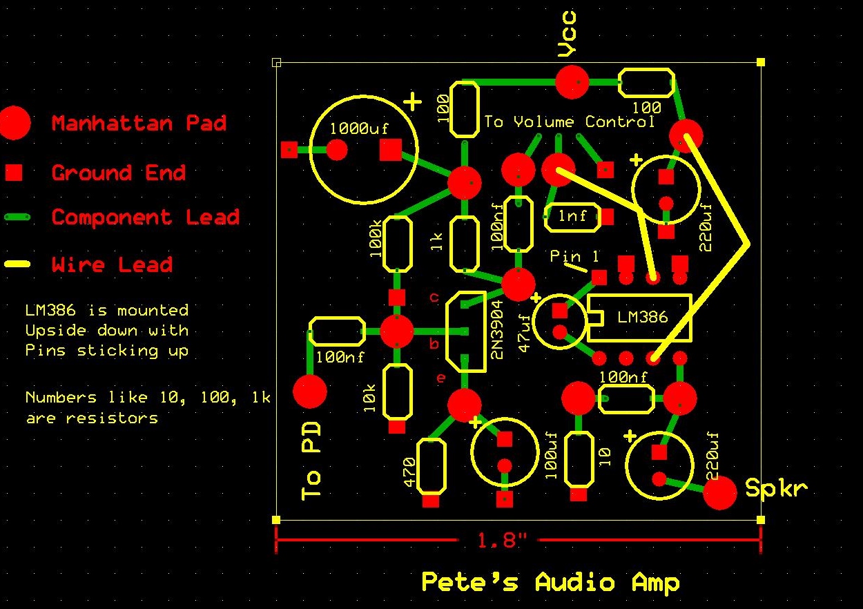
See the Note abut the LM386 being installed Dead Bug.....
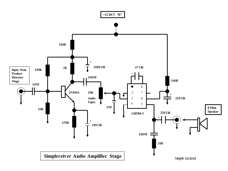
Those wanting more juice (and what is in my Simpleceiver) is the circuit below which uses a low noise version of the NE5534 followed by the LM380. This hummer is good for in excess of 1 watt output. This circuit was originally developed for use in my KWM-4 and simply reproduced for use in the Simpleceiver -- no wimpy audio here.
Either circuit will work well with the project although the first probably has less current drain which may be a consideration for those who simply have to drag a rig out to the middle of nowhere and try to make 10000 QSOs on a Saturday afternoon. Most of my stuff is intended to stay on the desk but for portability the 2N3904/LM386 is a less of a current drain.

I got overcome by other commitments on 8/22 and today does not look any better. But I still plan to build a version of the 1st amp on a small chunk of perfboard. Stay Tuned.
We also have a updated layout from Bob N7SUR for the ExpressPCB that includes the TI transformer and adds a bit more space (for those of us suffering from FFS, AKA Fat Finger Syndrome).
We also have a updated layout from Bob N7SUR for the ExpressPCB that includes the TI transformer and adds a bit more space (for those of us suffering from FFS, AKA Fat Finger Syndrome).
Pete, N6QW
8/22/2017 ~ This project is one fast moving Freight Train and I just hope I don't get run over in the process as I have to really move fast to keep up. Let me explain.
Previously I had mentioned about building techniques such as my approach using the CNC machine or the W1REX MePads or plain old Manhattan style. Several blog readers taking this one step further have designed boards using technologies such as ExpressPCB, Toner Transfer and KiCAD. Shortly I will be showing their work BUT these kind souls have also provided links where you can download the board information/files so that you can have your own PC Boards fabricated.
Since the same basic template will be used for many parts of the project having access to multiple universal boards will facilitate the building of the entire project and also hopefully minimize wiring errors. While not a sure cure for mistakes (or is it misteaks) it does remove some of the obstacles.
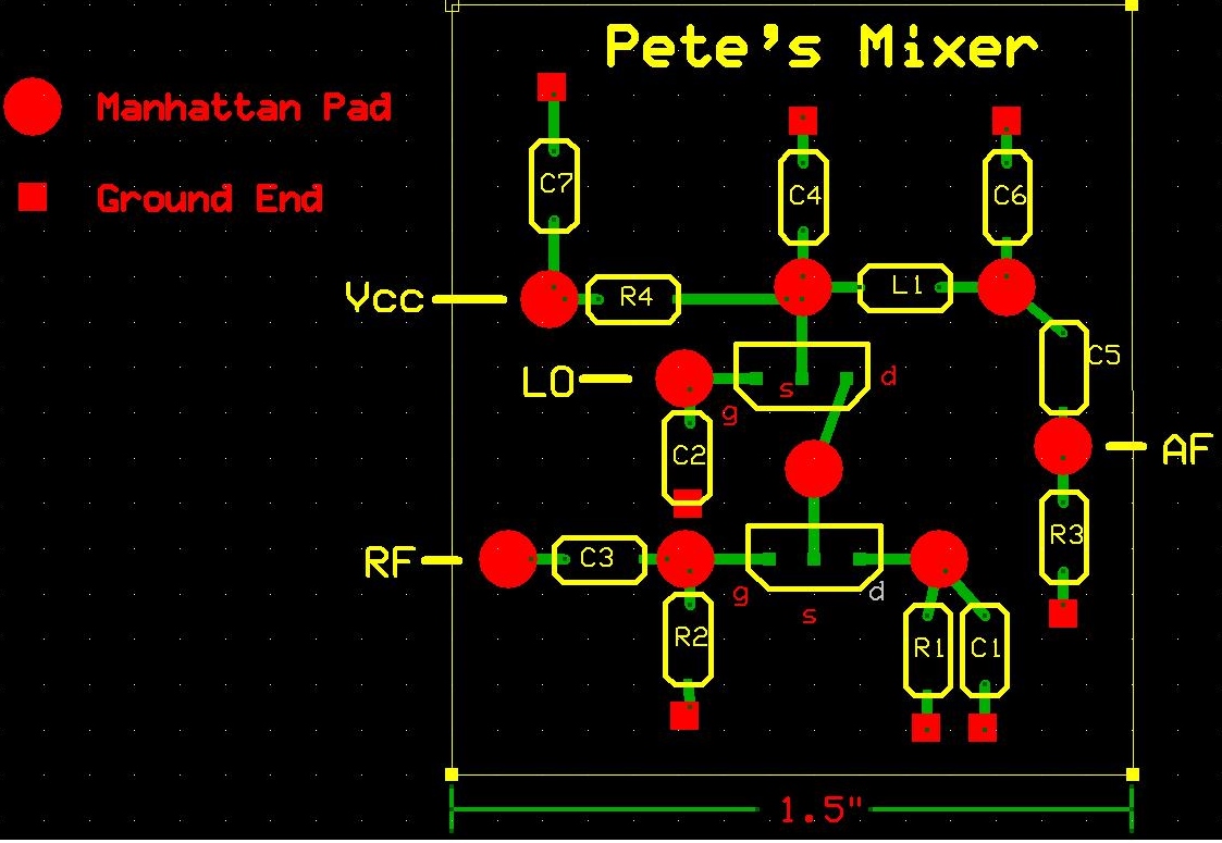
The first input I got on a board design was from Bob N7SUR who came up with a Manhattan Pad layout using ExpressPCB and the board is small like 1.5 X 1.7 inches. Since there will be many such boards in the project a compact layout keeps the overall project to a reasonable size. I should note that Bob made this layout before I revised the layout to include T1 which is the matching transformer but the board will work as is -- just install the transformer in place of C3 and add the 22K in lieu of C2 and the Coupling cap to Gate 2. Thanks Bob.
Next we have some help from VK land with Greg who has designed a Board using KiCAD which seems to be a favorite among many homebrewer's. Below is the output from the KiCAD files and here is a link where you can download the KiCAD files. Thanks Greg.
This is a Zip file which Greg has temporarily placed in this location. We are evaluating a better method for some sort of repository to hold the info so it can be downloaded. That may involve the use of the github of which I am in the dark ages of how to execute so that will require some study on my part.

Finally we have DuWayne KV4QB. If do a search on this blog from the earlier project documentation you will see that DuWayne provided a complete Schematic of the Simpleceiver. Now this time he has provided a layout using the Toner Transfer method and there are also link to a dropbox where you can download the artwork.

And for those of you with better eyesight than N6QW here is a SMD version from DuWayne.

Here is the dropbox link from DuWayne:
Thank you Bob, Greg and DuWayne! Given this range of options for the build -- there is no reason for you to remain seated on the Couch. Start collecting those parts! This is exciting to see so much interest in the rebirth of this project.
Later today, I hope to add an audio amplifier to this posting so you can start collecting the amplifier parts and building the 1st stage of the project. Just to mix things up I plan on building the audio stage on a piece of perfboard currently available from All Electronics --- the board size is about 1.5" X 1/5".
BTW any suggestions about the best way to archive the files for downloading would be most appreciated.
73's
Pete, N6QW
8/21/2017 ~ Some updates and new information. First let me say that I have received over a dozen replies (world wide) from fellow homebrewer's who want to join in on the fun.
I have updated the schematic / pictorial layout shown yesterday to include a matching transformer into Gate #1 and to add the pieces not originally shown for Gate #2. The Gate #1 matching transformer is a 3 turn Primary to a 20 Turn Secondary wound on a FT37-43 core. I tried to keep all interfaces at 50 Ohms and this transformer T1 matches 50 Ohms to the forced input of 2.2K Ohms. The match is 1:44 and with the 3/20 Turns Ratio you get 1:44.4 (close enough for Government work. I also included the schematic from the LT Spice Simulation. If I can figure out how to link to the .asc file I will do that otherwise you will have to replicate the drawing in your LT Spice.
I did receive a technical question about the 2.2K resistor on Gate #1 and was referred to Solid State Design for the Radio Amateur Chapter 6, Page 124 Figure 19 where we have a Naked Gate #1. (No 2.2K). Well I responded that I got that from Hayward and never questioned its use. Actually in going back over my hen scratch notes I found that it was DeMaw in his W1FB Design Notebook Page 139, Figure 5-22 where he uses 5.1K on Gate #1 for several of the 40673's. I think I might have used the 2.2K to facilitate a 1:44 match.
In my response back to that input I suggested that different values of the Gate #1 resistor be tried (including no resistor) and use LT Spice to simulate the response. That should extend the comfort zone as to whatever to use, if any resistor, and what value. Let's use the tools we have.
The J310's can be replaced with 2N3819 with a change in the Source resistor to 120 Ohms. So Ok here comes the question why did you do that -- well I used LT Spice and found that 120 Ohms worked best with the 2N3819 and 680 Ohms worked the best with J310 -- use the tools we have.
I am presenting this circuit now so that prospective builders can start collecting parts. Noteworthy here is that the simulation used the LO (BFO) frequency of 7.030 MHz. This means you could build a simple 7.030 MHz Oscillator (Crystals can be purchased through ESE, QRP SPRAT or Halted Specialties [HSC] out here on the left coast.) Then with a simple oscillator connected like a VXO you could tune around the 40 Meter QRP CW watering hole. Or build the amazing PS Kang 160 KHz VXO with a single 7 MHz ceramic resonator and tune the whole band.
The next piece that I will highlight is the audio amplifier and then the Band Pass Filter and finally the J310 DGM RF amplifier. So while you are collecting parts for the PD get two sets as you will need those for the RF amplifier stage. BTW the RF amp stage will have a gain control. The last piece will be the LO and we are looking at a conventional Analog VFO (shudder), a crystal mixed heterodyne VXO and finally the Si5351. The Si5351 is the most desirable in a configuration where this is turned into a SSB transceiver as it can supply the LO and BFO all from the same board.
There was a 22 part series on the Simpleceiver that was done in late 2015 and early 2016. Using the search block on this blog you can be connected to that earlier work.
Stay Tuned & 73's
Pete N6QW
8/20/2017 ~ I have already received some feedback from several readers about their desire to participate in this project. So here is a little more information about how the project will progress.
There are many ways to initiate a radio project with some advocating building the toughest nut to crack as a first item such as the Analog VFO or a Digital VFO and then follow on with the easy stuff. While my preference is to always start at the back end and work your way forward so that what is built and tested then becomes part of the test system for the next stage to be added. That is how this Simpleceiver Plus project will progress and the first element will be the audio amplifier stage.
My plan is to try to use / reuse a common circuit in as many places as possible since that affords an opportunity to minimize the numbers of different parts used and a common building block enables/facilitates trouble shooting. That common building block is two J310s configured (mostly) as a Dual Gate MOSFET (DGM). I now have this common J310 DGM circuit element configured as a Microphone Amplifier, RF Amplifier, IF Amplifier, Oscillator, Mixer and Product Detector -- we are just getting started here. Along with this is the extensive use of LT Spice Simulation software (a free download from Linear Technology). Thus you have a solid technical basis for the design that has been simulated with known results and thus enables experimentation to evaluate circuit changes and improvements.
Because the DGM has four connections much like a Tetrode vacuum tube, Gate 2 affords us the opportunity to use this port as a secondary signal input port for applications such as in a Mixer or Product Detector. If however a variable voltage is applied to Gate #2 it then becomes a variable gain amplifier stage which is desirable for application involving the addition of Manual Gain Control or AGC. Hopefully you are now seeing the rationale behind my choice of design approach. Stay Tuned!
Pete
N6QW
There may be a good chance of a group project being undertaken called the Simpleceiver Plus, much like the LBS project. Only this time it will be done incrementally with hopefully the blog readers following right along as we build first a Direct Conversion Receiver and then either a DSB Transceiver or an uptown SSB Transceiver.
In line with keeping it simple get a stock of J310 FET's as these will form the basic building blocks for the project. Most of the circuits will use homebrewed Dual Gate MOSFET's made from two J310's. In many cases LT Spice Simulations will be provided so that the builder can "tinker" with the circuit elements.
Below are two videos where you can see & hear the Simpleceiver in action. Yes, initially it has the dreaded Analog VFO and a homebrew Crystal Filter built NOT Using the Dishal Method. Listen closely to how the filter sounds. The IF is at 12 MHz so a 5 MHz LO gives you the 40 Meter Band.
Let me know if you would be interested in building along with me on this project.
73's
Pete N6QW